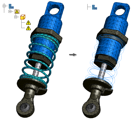
The mesh is first applied to the base configuration. If a mesh failure occurs in the base configuration, the mesh process halts and a warning displays.
Mesh failures can occur for various reasons, and are reported in:
- The Mesh progress dialog box.
- An error label and leader on the model in the graphics area. The leader indicates where the failure occurred. A short situation-specific recommendation for resolving the failure is provided. You can manipulate the mesh label as appropriate. Note: If the failure occurs in a part with its visibility turned off, the mesh label does not appear in the graphics area.
- In the browser, under the Mesh node, a Failures folder populates with error nodes corresponding to the error labels.
If a parametric study witnesses a failure, you receive a warning, but the remaining configurations continue to be meshed.
Failure nodes have a Visibility command on the context menu.
View and hide mesh failure labels
- To view additional information in the graphics area, in the browser, click the mesh failure label or the mesh failure node.
- To hide the information, click another failure label or node, or click empty space in the graphics window.
Exclude components with mesh failures

In mesh failure cases, the Mesh dialog box displays the ![]() Mesh failed message, and the browser displays the Failures folder
Mesh failed message, and the browser displays the Failures folder ![]() under the Mesh node
under the Mesh node ![]() . The Failures folder contains the components affected by mesh failures.
. The Failures folder contains the components affected by mesh failures.
- Expand the Failures folder.
- Right-click a component, and click Exclude From Simulation. The Update Required icon
 displays next to both the Mesh node and Contacts node
  .
. - Right-click the Mesh node, and click Update Mesh.
- Right-click the Mesh node and click Mesh View. The excluded component is no longer meshed.
- Continue with your simulation.
