
To Add Joints in Moving Assembly Simulations
The Follower is designed to slide through a portion of the Guide component. However, to hold the Follower Roller against the Cam, specify a spring between the Follower and Guide components. Dynamic Simulation has a joint for doing that and more, the Spring/Damper/Jack joint.
On the ribbon, click Dynamic Simulation tab
 Joint panel Insert Joint and in the list, select Spring / Damper / Jack joint.
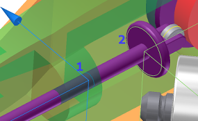
On the Guide component, select the hole profile where the follower passes through the Guide (1).
Select the edge profile where the spring contacts the follower.
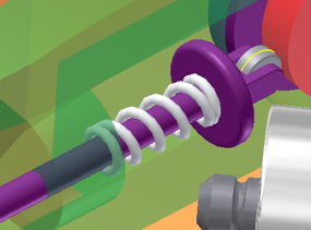
The result is a spring joint in the browser and a graphic representation of a spring. The representation is deformable and has action-reaction forces, but does not have mass.
In the browser, in the Force Joints folder, right-click the Spring joint and click Properties.
In the main section of the dialog box, set:
Stiffness = 2.500 N/mm
Free Length = 42 mm
Expand the dialog box and set:
Radius = 5.2 mm
Turns = 10
Wire Radius = .800 mm
Click OK. The spring properties and graphical display update.
In the browser, in the External Loads folder, right-click Gravity and click Define Gravity. Alternatively, you can double-click the Gravity node. If necessary, clear the Suppress check box.
Select the Case edge, as shown in the following image, to specify a vector for gravity.
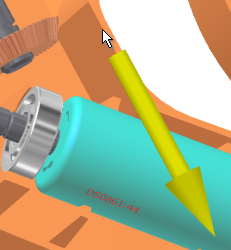
Click OK.