
To Import Files as an AnyCAD Reference or Convert Model
Import current versions of 3rd party files.
What's New: 2023.2, 2024, 2025
Translate files
You can open or import part and assembly files from other CAD systems. You can also place part and assembly files as components into new or existing Inventor assemblies.
For a list of supported file types, refer Translator Support.
Do one of the following:
To import to a new file select:
- File
 Open Import CAD Formats
 - Get Started tab Launch panel Import CAD Formats
When you import a file, Inventor automatically detects whether the imported file is a part or assembly and creates the new document accordingly. For example, to import a 3rd party assembly file as a part, you must first create or have a part file open, and then import the 3rd party assembly file into the part file.
- File
To import into a part file select:
Manage tab
Insert panel Import- 3D Model tab Create panel Import
- 3D Model tab
To import into an assembly, select Assemble tab
Component panel Place Imported CAD.
In the applicable dialog box, set the Files of type to view the available files.
Select the file to import and click Open.
To edit the import options after importing, right-click on the file in the browser, and select Edit Import from the context menu.
To Import as an ANYCAD Reference or Convert Model
In Home, click Open, set the file type to the desired format, then navigate to and select a file and click OK.
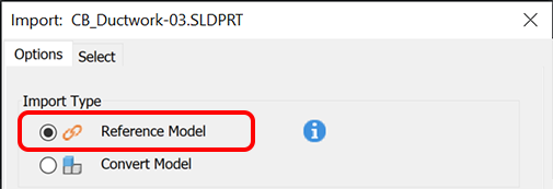
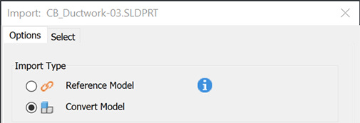
In the Import dialog, on the Options tab, specify the Import Type. Select one of the following:
Reference Model: to maintain a link to the selected file which enables you to monitor and update as the model changes. Use this option if the design is evolving and you are not required to edit the referenced model.
Convert Model: to create a new Inventor file which is not linked to the original. Use this option if you plan modify the model for a new design.
The Object Filters section allows you to specify the type of geometry to import. Specify the type of geometry to import:
- Solids imports solid bodies and water tight stitched shells as individual solid bodies.
- Surfaces imports surface bodies.
- Meshes imports meshes. Mesh data is for visualization purposes only.
- Graphical PMI
- Wires
- Work Features imports the desired work geometry.
- Points
- UCS responds to visibility setting, imports UCS geometry (work axes, planes, and point).
Inventor Length Units: In the Inventor Length Units field, specify the type of Inventor length units to use for the imported geometry and parameter values. The unit value selected only changes the length units for the new document. The length and other units for the document can be viewed in the Document Settings dialog box on the Units tab.
The following options are only available if Convert Model is selected as the Import Type. Specify how to import solids into the file:
Assembly Options:
- Assembly preserves the source structure.
- Multi-body part imports an assembly as solid bodies in a single part.
- Composite PartThe composites are created from the levels, layer, or groups. Each level, layer, or group is created as an individual composite feature that has the same name as the level, layer, or group it originates from. Each composite feature has its own browser node that is a child of the root node.
Part Options
- Composite imports the assembly as a single composite feature in the part environment.
- Individual imports the assembly as individual surface features in the part environment.
- Stitch (IGES and STEP files only) stitches several edge-matched surfaces or faces together.
- Construction
File Name: If applicable, provide a file name to avoid name duplication issues. Specify a prefix or suffix to add to the file name.
Output Location:
Source Path - outputs the file in the source file location.
User Path - browse to the folder where you want the output file to be placed.
Workspace - outputs the file in the workspace location.
Save In Subfolder - when selected, outputs the file to a subfolder when there is more than one file type being imported.
Note: The path selection persists and is available for use with subsequent import tasks, whether a single file or a batch process.
To selectively import files from CATIA, Solidworks, Pro-E/Creo, NX, Alias, Step, Iges, and Rhino, click the Select tab.
Click OK to import the file.
Importing Fusion Files
To share data between Inventor, a desktop application, and Fusion, a cloud based platform, there are a few things to set up.
For detailed information, see To Import Fusion Files as an AnyCAD Reference Model.
Importing Alias files
The geometry is created in Inventor using the same colors as assigned in Alias. However, texture maps included in the Alias definition are not translated to the Inventor file.
Importing CATIA V4 Files addendum
Open and change models created in CATIA V4 (all versions). Autodesk Inventor translates assembly and part files, solids, multi-solids, surfaces, and more. After the import operation is complete, you have a base feature or features which match the geometry and topology of the original file. Use Autodesk Inventor commands to adjust the base features and add new features to the feature tree.
These types of CATIA V4 files can be imported:
*.model
*.session
*.dlv3
*.exp
Note: When you open a .exp file, Inventor displays the models it contains in the CATIA V4 Model Selection dialog box. Select the appropriate .model file to import and click OK.
If you select to import mesh data, Inventor creates mesh features  and groups them under mesh folders
  in the browser. The mesh features are for visualization purposes only and cannot be modified. You can right-click the mesh features or folders to access the context menu and select to show mesh edges, change visibility, and more.
After changing the file, you can continue to open it in Autodesk Inventor.
Import CATIA V5 Files
Autodesk Inventor translates assembly and part files, solids, multi-solids, surfaces, and more. After the import operation is complete, you have a base feature or features which match the geometry and topology of the original file. Use Autodesk Inventor commands to adjust the base features and add new features to the feature tree.
These types of CATIA V5 files can be imported:
*.CATPart (part)
*.CATProduct (assembly)
Note: Inventor automatically translates CATIA V4 files referenced by *.CATProduct files.*.cgr
Note: Mesh data from .cgr files are for visualization purposes only.
If you select to import mesh data, Inventor creates mesh features and groups them under mesh folders in the browser. The mesh features are for visualization purposes only and cannot be modified. You can right-click the mesh features or folders to access the context menu and select to show mesh edges, change visibility, and more.
After changing the file, you can continue to open it in Autodesk Inventor.
Import JT Files
Autodesk Inventor translates assembly and part files, solids, multi-solids, surfaces, and more. After the import operation is complete, you have a base feature or features which match the geometry and topology of the original file. Use Autodesk Inventor commands to adjust the base features and add new features to the feature tree.
Import Pro/ENGINEER and Creo Parametric Files
Open and change models created in Pro/ENGINEER and Creo Parametric. Autodesk Inventor translates assembly and part files, solids, multi-solids, surfaces, and more. After the import operation is complete, you have a base feature or features which match the geometry and topology of the original file. Use Autodesk Inventor commands to adjust the base features and add new features to the feature tree.
These types of Pro/ENGINEER files can be imported:
- .prt (part)
- .asm (assembly)
- *.g (Granite)
- .neu (Neutral)
Import Parasolid Files
Open and change models created in Parasolid (up to version 28.0). Autodesk Inventor translates assembly and part files, solids, multi-solids, surfaces, and more. After the import operation is complete, you have a base feature or features which match the geometry and topology of the original file. Use Autodesk Inventor commands to adjust the base features and add new features to the feature tree.
These types of Parasolid files can be imported:
- *.x_t (text)
- *.x_b (binary)
Import Rhino Files
The import process creates base features in Inventor representative of the geometry and topology in the source file. You can use Inventor commands to adjust the base features and add new features to the Inventor feature tree. You cannot modify the original definition of the base features.
Import SolidWorks Files
Open and change models created in SolidWorks. Autodesk Inventor translates assembly and part files, solids, multi-solids, surfaces, and more. After the import operation is complete, you have a base feature or features which match the geometry and topology of the original file. Use Autodesk Inventor commands to adjust the base features and add new features to the feature tree.
These types of SolidWorks files can be imported:
- *.prt, *.sldprt (part)
- *.asm, *.sldasm (assembly)
Import NX Files
Open and change models created in NX (formerly UGS NX). Autodesk Inventor translates assembly and part files, solids, multi-solids, surfaces, and more. After the import operation is complete, you have a base feature or features which match the geometry and topology of the original file. Use Autodesk Inventor commands to adjust the base features and add new features to the feature tree.
These types of NX files can be imported:
- *.prt (part)
- *.prt (assembly)
Import STEP or IGES Files
If an imported STEP or IGES file contains one part, it produces an Autodesk Inventor part file. If it contains assembly, it produces an assembly with multiple part files.
See Productivity Tools for more information about the command to Rename Browser Nodes.
Import SAT Files
You can import an SAT file. The curves, surfaces, and solids are saved in an Autodesk Inventor file, and no links are maintained to the original file.
If an imported SAT file contains a single body, it produces an Autodesk Inventor part file with a single part. If it contains multiple bodies, it produces an assembly with multiple part files.
Import SMT Files
You can import an SMT file type extension from Autodesk Shape Manager (ASM) that can be used for interoperability operations among Autodesk products.