
Volumetric shrinkage at ejection result
The Volumetric shrinkage at ejection result shows the volumetric shrinkage for each area expressed as a percent of the original modeled volume.
For analysis sequences that include
- Pack
Volumetric shrinkage at ejection is the decrease in local volume from the end of the cooling stage to when the part has cooled to the ambient reference temperature (the default value is 25°C/77°F).
Volumetric shrinkage calculations begin once the cavity is filled and continue to be recalculated until the PVT is set by either pressure decaying to zero or material completely frozen. The calculations are based on the difference between the current pvT state and the reference state (where the pressure p is zero and temperature T is the specified ambient temperature):
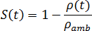 | (1) |
As the mass of an element changes (for example, with polymer flow during packing), shrinkage continues to change with each change in the element's pvT state. Once the mass stops changing, the element's current pvT state is fixed in the shrinkage calculation as the reference state.
The mass of an element stops changing when the cavity pressure has decayed to zero. After this, the volumetric shrinkage becomes a constant. However, if the holding pressure is removed before the material is frozen or while the pressure in the cavity is still non-zero, the volumetric shrinkage may rebound due to possible backflow into the nozzle or other warmer areas of the part.
Once the part has filled, or a short-shot has occurred, the software checks to determine whether cooling can start at each injection location. Cooling at a specific injection location starts when the flow rate at that injection node drops below a defined small value for two consecutive time steps. Until that time, the node is considered at melt temperature. Thus, different injection locations can start cooling at different times. Once a location has started cooling, it will continue cooling regardless of the flow rate. See Injection location temperature during packing and cooling for more information.
Using this result
This result can be used to detect sink marks on your model. High shrinkage values could indicate sink marks or voids inside the part.
To minimize warpage, the variation in volumetric shrinkage throughout the cavity should be minimized. If the material has been characterized for shrinkage (thermoplastic materials only), the magnitude of the volumetric shrinkage can also be compared to the range of volumetric shrinkage values found in the Shrinkage Molding Summary table, which will provide a guide to typical average volumetric shrinkage values for the material.
To access the Shrinkage Molding Summary table, right-click the material in the Study Tasks pane and select Details. Select the Shrinkage Properties tab from the Thermoplastics material dialog.
Volumetric shrinkage can be controlled by the use of packing profiles.
Things to look for
When viewing the Volumetric shrinkage at ejection result, watch for the following:
Localized areas of high shrinkage can result in internal voids or sink marks when the part cools.
Shrinkage values should be uniform throughout the part. This is important for good packing of the material, ensuring good structural and visual integrity of the part. Use a packing profile to make the shrinkage more uniform.
Negative volumetric values indicate expansion rather than shrinkage. Avoid negative shrinkage on ribs because this can cause ejection problems.
Check that values are in the expected range for the material, noting the following:
Materials that shrink isotropically have a linear shrinkage that is approximately one third of the volumetric shrinkage.
For molded materials, the linear shrinkages in the thickness, flow, and transverse directions depend on the effects of relaxation and orientation.
For shell-like geometries, the shrinkage in the thickness direction should be higher than the shrinkage in the plane of the part. Shrinkage in the thickness direction is likely to be greater than one third of the volumetric shrinkage, and in-plane shrinkage should be less than one third of the volumetric shrinkage. Many mold features act as constraints on in-plane shrinkage. When fiber-filled material are used, the orientation of the fibers in the plane of the part will limit shrinkage in this direction. Shrinkage in the thickness direction is relatively unconstrained.