
Anchors
Define anchors by one, two, or three nodes.
Using one anchor defines the origin for the deflection plot. The following figure is using a single anchor. Initially, Best fit is used to display deflection plots. By assigning a single anchor, you are moving the best fit so the location of the anchor becomes zero. Comparing multiple studies using a single anchor ensures a common zero location, without artificially changing the perceived shape of the part.
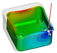
Figure 1: Part with single anchor being used
Most of the time three anchors are used. By using three anchors, a new coordinate system is defined for the deflection result it is applied to. The part is also constrained by the three locations so the deflection plots are oriented to the new coordinate system. In the following figure, the part has an anchor plane defined on the assembly screw bosses. Using the Z-deflection plot, you can determine how parallel the sealing surface is to the plane of the anchor plane on the screw bosses. The assumption is the sealing surface comes together with its mating part perpendicular to the plane formed by the three anchors.
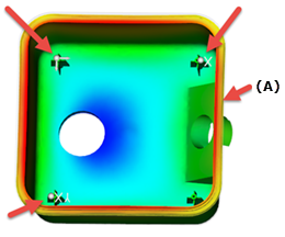
Figure 2: A = Sealing surface (Rim)
Using a single anchor on the sealing surface cannot be used to determine how parallel the surface is. A single anchor is better for determining a flatness tolerance. Using a single anchor zeros out the anchor location, making it easier to evaluate the flatness of the sealing surface. Either method is acceptable depending how the tolerance for the sealing surface is specified and how warpage is measured for the molded parts.