
Reference: John Goldak, Aditya Chakravarti, and Malcolm Bibby. A new finite element model for welding heat sources. Metallurgical transactions B, 15(2):299-305, 1984.
*GOLD
r1, r2, r3, r4, r5, r6
The heat source definition is illustrated in the figure below.
r1: r*8: efficiency. Default 1.d0
r2: r*8: b axis multiplier. Default 1.d0
r3: r*8: c1 axis multiplier. Default 1.d0
r4: r*8: c2 axis multiplier. Default 4.d0
r5: r*8: f1 factor. Default .6d0
r6: r*8: f2 factor. Default 1.4d0
- The a axis dimension is set as the melt pool radius (typically about equal to the laser spot size) as defined in *LSRF
- r1 should be set to the absorption efficiency value.
- The b axis dimension is set as r2*a
- The c1 axis dimension is set as r3*a
- The c2 axis dimension is set as r4*a
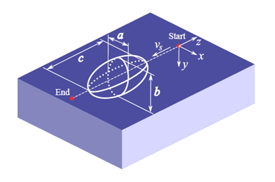
Schematic of the Goldak heat source
Best Practices: For moving-source powder bed, LENS® or other thin layer deposition, the b parameter, which controls the Z axis of the double ellipsoid volume of the heat input model, should be set to r2 = 0.6, which should give a fairly accurate representation of the melt pool, as described in Goldak’s article referenced above, and other modeling literature.
For thicker depositions, r2 should be adjusted so that the laser depth and layer height are identical, e.g.
r2 = layer height/laser radius
This is performed to ensure the entire deposition is melted. If there are unactivated elements or layers in the simulation results, check to see if the r2 value satisfies the above condition.