
*LSRP
r1, r2, r3, r4, r5, r6, i1, r7, r8, r9, [r10]
r1: r*8: power
r2: r*8 radius of melt pool
r3: r*8: travel speed
r4: r*8: layer thickness
r5: r*8: hatch spacing (gap width)
r6: r*8: deposition time from layer to layer
i1: i*4: number of layers
r7: r*8: initial vector angle [no longer editable]
r8: r*8: vector angle change from layer to layer
r9: r*8: x width of part
r10: r*8: y width of part (if omitted set to r9)
This card generates a laser path for a rectangular patch with an area of r9 x r10. The path is stored as text file in <filename>.lsr, and used for the analysis. The value of the top substrate z coordinate is defined by the DDM! The laser path extends out of the part by a distance equal to the melt pool radius (r2).
Typically the radius of the melt pool (r2) is about twice the radius of the laser beam.
The figure below depicts an example schematic of the first two build layers using paths generated using *LSRP.
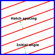
Layer 1
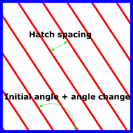
Layer 2