Creating toolpaths for additive manufacturing processes always involves working with geometry. With a few exceptions only 2D geometry comes into place, because toolpaths are generated for each layer of sliced 3D objects. The following picture demonstrates all buildstyle processing steps being done by the Advanced Toolpath Utility build processor, before any toolpath creation actions can be started with buildstyle projects:
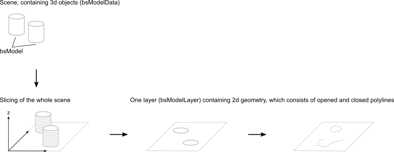
It starts with a scene of 3D meshes from the parent application (i.e. Netfabb), which is passed to the Advanced Toolpath Utility build processor mesh by mesh. From within buildstyle projects the scene can be accessed using bsModelData objects. Each mesh (model) is stored at the bsModelData object as a bsModel object.
The Advanced Toolpath Utility buildstyle processor slices the whole scene and stores a bsModelLayer object for each slice (layer). Every layer contains 2D geometry data for all meshes, that intersected with that layer. These layers are filled with polylines (sets of connected points) and these polylines can either be closed (start and end point are connected) or opened (start and end points are not connected).
These polylines are the source for the toolpath creation process and they contain all information, which is needed to generate toolpaths. The Advanced Toolpath Utility build environment, however, offers two other types of geometric objects. These are bsPathSet and bsIsland. Both types are lists of polylines. Objects of type bsPath may contain several opened or closed polylines. Objects of type bsIsland may contain several closed polylines.
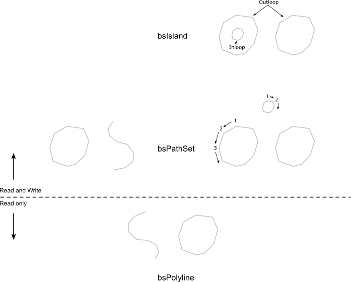
Polylines can only be accessed by bsModelLayer objects using a write protected bsPolylineIterator.
A bsPolylineIterator is used to get 2D geometry from a bsModelLayer. Either all 2D geometry or 2D geometry of the following types can be accessed with bsPolylineIterator instances:
- Closed polylines (bsPolylineIterator.nIslandBorderPolygons) of part and support geometry.
- Open polylines (bsPolylineIterator.nLayerOpenPolylines) of part and support geometry.
- Toolpath polylines (bsPolylineIterator.nLayerExposure). This type of polylines will be discussed at the toolpath creation chapter.
PathSets are collections of polylines (either opened or closed) and they allow creation, modification and deletion of polylines.
- A bsPathSet is used to create, modify or remove 2D geometry on bsModelLayer instances.
Islands are collections of closed polylines. The interesting aspect of an island is, that it uses the geometric direction of the polyline points to identify polylines either as an area or as a hole. Clockwise oriented polylines are holes, counterclockwise oriented polylines are areas. This is used to build non solid (hollow) objects.
- A bsIsland is used to differentiate between areas and holes. It depends on closed polylines.
Tips for dealing with bsIsland and bsPathSet
- Instead of bsIsland, always think of bsIslandSet, because bsIsland instances might contain more than one island (The takeOutDiscreteArea function returns each island one by one). The naming has evolved historically and if would have been better to work with bsPathSet and bsIslandSet instances.
- Neither bsPathSet nor bsIsland objects allow to access the polyline geometry, but all copy functions are working on geometry only. Copying a bsIsland to a bsPathSet adds the island's geometry to the path set. As for the bsPathSet example, the geometry of anotherBsPathSetObj is copied to myBsPathSetObj.
So now that we know about Advanced Toolpath Utility's geometry API structure, let's have a look at examples.
Using the Geometry Buildstyle Examples
All geometry example buildstyles benefit from an optional function that can be used within buildstyles.
exports.preprocessLayerStack = function(modelDataSrc, modelDataTarget, progress)
{
}
This function gets called as soon as the buildstyle processor is done with input geometry processing. The modelDataSrc object contains the processed geometry and the modelDataTarget object is empty. All processing steps following preprocessLayerStack will use the modelDataTarget object for geometry processing. Within preprocessLayerStack, the buildstyle code is used to generate the target model data by copying data from the source to the target model or by constructing new layer geometry data.
The example buildstyles don't use any meshes from the input geometry at all. The preprocessLayerStack function is used to construct geometry exclusively within the buildstyle. Of course, this isn't a real world example, but it is a good start to get familiar with Advanced Toolpath Utility's geometry concept.
All buildstyles will refuse to work, without having any input geometry, so it is necessary to load a geometry file even if it isn't used later on.
For a start, use the Advanced Toolpath Utility to open the first geometry example buildstyle at C:\ProgramData\Autodesk\ATU\ATU-Examples\tutorial-projects\geometry\01_2d-Geometry\. Now, open the Input Geometry Files widget and add the tree_sample_part.stl file as a part to the project. The layer thickness should be 100 micro meters. It can be found ZIP-compressed at C:\ProgramData\Autodesk\ATU\ATU-Examples\Geometry files\.
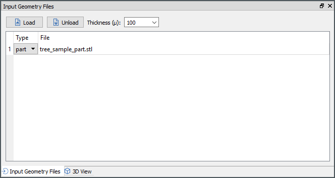
Hit Compile and check, if you can see a red rectangle at the exposure preview widget.

Creating Layer Geometry
The buildstyle can be found at C:\ProgramData\Autodesk\ATU\ATU-Examples\tutorial-projects\geometry\01_2d-Geometry\.
The first example buildstyle, which hopefully is now visible on the computer screen, creates a model with ten layers. Each layer contains a rectangle (a closed polyline). The buildstyle consists of one JavaScript file only (main.js).
It imports a few internal script objects, that are used for geometry processing and adds simple about and machine information structures. All other functions are empty, except for preprocessLayerStack and roundVal.
function roundVal(value){
    return Math.round(value * 100) / 100;
}


exports.preprocessLayerStack = function(modelDataSrc, modelDataTarget, progress)
{
  if(ENABLE_LOGGING){
    process.printInfo('************************************************************\nPreprocessLayerStack\n');
    var message = '';
  }
  message += 'Adding an empty model.' + '\n';
  modelDataTarget.addEmptyModel();

  var modelCount = modelDataTarget.getModelCount();
  message += 'Current model count: [ ' + modelCount + ' ]\n\n';
  if(modelCount > 0)
  {
    message += 'Retrieving first model.\n\n';
    var model = modelDataTarget.getModel(0);

    var layerThickness = modelDataSrc.getLayerThickness();
    message += 'Current layer thickness: [ ' + layerThickness + ' ]\n';
    var minZVal = modelDataSrc.getZeroPosZ() + layerThickness;
    message += 'Current minimum z value: [ ' + minZVal + ' ]\n\n';

    message += 'Creating 10 layers...' + '\n\n';
    var currentZVal=minZVal;
    var rectangleSize = 20.0;
    var half_rectangle = rectangleSize / 2.0;
    // For each layer
    for(var index=0; index<10; index++)
    {
      message += 'Creating layer: [ ' + index + ' ]\n';
      model.createModelLayer(currentZVal);

      var currentLayer = model.getModelLayer(currentZVal);
      message += 'Creating new path set.\n';
      var rectangle = new PATH_SET.bsPathSet();
      message += 'Creating first point.\n';
      var point1 = new VEC2.Vec2(half_rectangle * -1.0, half_rectangle);
      message += 'Creating second point.\n';
      var point2 = new VEC2.Vec2(half_rectangle * -1.0,half_rectangle * -1.0);
      message += 'Creating third point.\n';
      var point3 = new VEC2.Vec2(half_rectangle,half_rectangle * -1.0);
      message += 'Creating fourth point.\n';
      var point4 = new VEC2.Vec2(half_rectangle,half_rectangle);
      message += 'Adding new path to path set using the already created points.\n';
      rectangle.addNewPath(point1,point2,point3,point4);

      message += 'No of paths in path set: [ ' + rectangle.getPathCount() + ' ]\n';
      message += 'Closing path, which is opened by default.\n';
      rectangle.setClosed(true);
      message += 'Is path closed?: [ ' + rectangle.isClosed() + ' ]\n';

      message += 'Adding path to model layer.' + '\n';
      currentLayer.addPathSet(rectangle, MODEL.nSubtypePart);

      message += '\n';
      currentZVal += layerThickness;
      rectangleSize -= 0.6;
      half_rectangle = rectangleSize / 2.0;
    }
  }
  if(ENABLE_LOGGING){
    process.printInfo(message);
  }
}
A lot of code is used to generate log messages. Without these log messages the code looks like this:
function roundVal(value){
    return Math.round(value * 100) / 100;
}

exports.preprocessLayerStack = function(modelDataSrc, modelDataTarget, progress)
{
  modelDataTarget.addEmptyModel();

  var modelCount = modelDataTarget.getModelCount();
  if(modelCount > 0)
  {
    var model = modelDataTarget.getModel(0);

    var layerThickness = modelDataSrc.getLayerThickness();
    var minZVal = modelDataSrc.getZeroPosZ() + layerThickness;

    var currentZVal=minZVal;
    var rectangleSize = 20.0;
    var half_rectangle = rectangleSize / 2.0;
    // For each layer
    for(var index=0; index<10; index++)
    {
      model.createModelLayer(currentZVal);

      var currentLayer = model.getModelLayer(currentZVal);
      var rectangle = new PATH_SET.bsPathSet();
      var point1 = new VEC2.Vec2(half_rectangle * -1.0, half_rectangle);
      var point2 = new VEC2.Vec2(half_rectangle * -1.0,half_rectangle * -1.0);
      var point3 = new VEC2.Vec2(half_rectangle,half_rectangle * -1.0);
      var point4 = new VEC2.Vec2(half_rectangle,half_rectangle);
      rectangle.addNewPath(point1,point2,point3,point4);
      rectangle.setClosed(true);

      currentLayer.addPathSet(rectangle, MODEL.nSubtypePart);

      currentZVal += layerThickness;
      rectangleSize -= 0.6;
      half_rectangle = rectangleSize / 2.0;
    }
  }
}
Functional Description (Step by Step)
Create and receive a new model on the target scene:
exports.preprocessLayerStack = function(modelDataSrc, modelDataTarget, progress)
{
  modelDataTarget.addEmptyModel();

  var modelCount = modelDataTarget.getModelCount();
  if(modelCount > 0)
  {
    var model = modelDataTarget.getModel(0);
.
.
.
The Advanced Toolpath Utility build processor uses two different approaches to identify layers. During toolpath calculation (makeExposureLayer) a layer index is passed to the function. For all other places the layer position has to be used to identify layers. Two different values are important:
- The minimum z position value.
- The layer thickness.
var layerThickness = modelDataSrc.getLayerThickness();
var minZVal = modelDataSrc.getZeroPosZ() + layerThickness;
Adding the layer thickness to the minimum z value iterates through all layers.
var currentZVal=minZVal;
// For each layer
for(var index=0; index<10; index++)
{
    currentZVal += layerThickness;
}
Ten new layers are created for the empty model, which was created at the beginning. Each layer can be received at the model object.
// For each layer
for(var index=0; index<10; index++)
{
    model.createModelLayer(currentZVal);
    var currentLayer = model.getModelLayer(currentZVal);
.
.
.
The rectangle on each layer is constructed using four points, which are added to a new bsPathSet object.
var point1 = new VEC2.Vec2(half_rectangle * -1.0, half_rectangle);
var point2 = new VEC2.Vec2(half_rectangle * -1.0,half_rectangle * -1.0);
var point3 = new VEC2.Vec2(half_rectangle,half_rectangle * -1.0);
var point4 = new VEC2.Vec2(half_rectangle,half_rectangle);

var rectangle = new PATH_SET.bsPathSet();
rectangle.addNewPath(point1,point2,point3,point4);
.
.
.
After all, the rectangle has to be closed, so that the start and the end points are connected and the bsPathSet object has to be added to each layer.
rectangle.setClosed(true);
currentLayer.addPathSet(rectangle, MODEL.nSubtypePart);
Examine Buildstyle Calculation Results
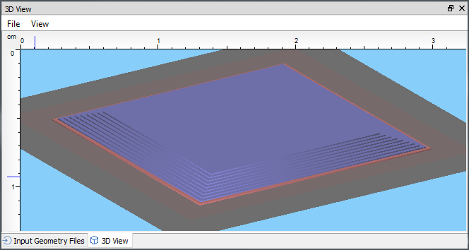
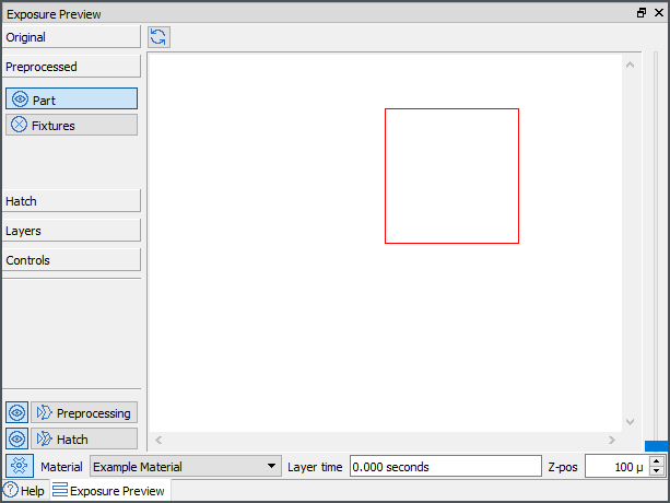
The exposure preview and the 3D view panel can be used to examine the calculation results. The exposure preview panel shows ten layers and their positions (preprocessed geometry has to be visible. Check the exposure preview's visibility options):
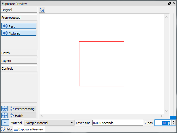
Cycling through the layers resizes the rectangle on the screen. The rectangle always gets a bit smaller on higher layers. The 3D view demonstrates this by showing a pyramid:
Clipping Operation
The buildstyle can be found at C:\ProgramData\Autodesk\ATU\ATU-Examples\tutorial-projects\geometry\02_Clipping\.
For the most part, this buildstyle is identical to the one above (01_2d-Geometry). It creates a model with ten layers and each layer contains a rectangle.
The new code is added as a new JavaScript file, called demonstration.js. For each layer the demonstration function is called after creating the rectangle. The constructed rectangle and the layer object are passed to the new function.
exports.demonstration = function(layer, rectangle)
{
  layer.addPathSet(rectangle, MODEL.nSubtypeSupport);

  var clippingRectangle = new PATH_SET.bsPathSet();
  var cPoint1 = new VEC2.Vec2(0.0, 15.0);
  var cPoint2 = new VEC2.Vec2(0.0,0.0);
  var cPoint3 = new VEC2.Vec2(15.0,0.0);
  var cPoint4 = new VEC2.Vec2(15.0,15.0);
  clippingRectangle.addNewPath(cPoint1,cPoint2,cPoint3,cPoint4);
  clippingRectangle.setClosed(true);

  var island = new ISLAND.bsIsland();
  island.addPathSet(clippingRectangle);

  //rectangle.clip(false, island);
  rectangle.clip(true, island);

  layer.addPathSet(rectangle, MODEL.nSubtypePart);
};
Functional Description (Step by Step)
The previously constructed rectangle is added to the layer as a support structure.
layer.addPathSet(rectangle, MODEL.nSubtypeSupport);
A new, intersecting rectangle is constructed:
var clippingRectangle = new PATH_SET.bsPathSet();
var cPoint1 = new VEC2.Vec2(0.0, 15.0);
var cPoint2 = new VEC2.Vec2(0.0,0.0);
var cPoint3 = new VEC2.Vec2(15.0,0.0);
var cPoint4 = new VEC2.Vec2(15.0,15.0);

clippingRectangle.addNewPath(cPoint1,cPoint2,cPoint3,cPoint4);
clippingRectangle.setClosed(true);
The new rectangle is added to an island:
var island = new ISLAND.bsIsland();
island.addPathSet(clippingRectangle);
The clip operation is used on both rectangles. It allows to keep either the intersecting or the non intersecting area by passing either true or false as first parameter. The current example keeps the intersecting area.
//rectangle.clip(false, island);
rectangle.clip(true, island);
The clipped rectangle is added to the layer as a part:
layer.addPathSet(rectangle, MODEL.nSubtypePart);
Examine Buildstyle Calculation Results
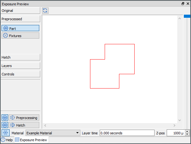
The exposure preview panel allows to show or hide part and support geometry. The Preprocessed section of the tab control on the left side can be used for this. Hiding the support structures (Fixtures) shows the clipped rectangle only:
| Keeping intersected area | Keeping non-intersected area |
|---|---|
|
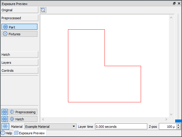
|
Boolean Operations
The buildstyle can be found at C:\ProgramData\Autodesk\ATU\ATU-Examples\tutorial-projects\geometry\03_Boolean-Operations\.
For the most part, this buildstyle is identical to the one above (01_2d-Geometry). It creates a model with ten layers and each layer contains a rectangle.
The new code is added as a new JavaScript file, called demonstration.js. For each layer the demonstration function is called after creating the rectangle. The constructed rectangle and the layer object are passed to the new function.
exports.demonstration = function(layer, rectangle)
{
  layer.addPathSet(rectangle, MODEL.nSubtypeSupport);

  var secondRectangle = new PATH_SET.bsPathSet();
  var cPoint1 = new VEC2.Vec2(0.0, 15.0);
  var cPoint2 = new VEC2.Vec2(0.0,0.0);
  var cPoint3 = new VEC2.Vec2(15.0,0.0);
  var cPoint4 = new VEC2.Vec2(15.0,15.0);

  secondRectangle.addNewPath(cPoint1,cPoint2,cPoint3,cPoint4);
  secondRectangle.setClosed(true);

  rectangle.booleanOpUnify(secondRectangle);
  //rectangle.booleanOpSubtract(secondRectangle);
  //rectangle.booleanOpIntersect(secondRectangle);

  layer.addPathSet(rectangle, MODEL.nSubtypePart);
};
Functional Description (Step by Step)
The previously constructed rectangle is added to the layer as a support structure.
layer.addPathSet(rectangle, MODEL.nSubtypeSupport);
A new, intersecting rectangle is constructed:
var clippingRectangle = new PATH_SET.bsPathSet();
var cPoint1 = new VEC2.Vec2(0.0, 15.0);
var cPoint2 = new VEC2.Vec2(0.0,0.0);
var cPoint3 = new VEC2.Vec2(15.0,0.0);
var cPoint4 = new VEC2.Vec2(15.0,15.0);

clippingRectangle.addNewPath(cPoint1,cPoint2,cPoint3,cPoint4);
clippingRectangle.setClosed(true);
One of three different boolean operations is used:
rectangle.booleanOpUnify(secondRectangle);
//rectangle.booleanOpSubtract(secondRectangle);
//rectangle.booleanOpIntersect(secondRectangle);
The processed rectangle is added to the layer as a part:
layer.addPathSet(rectangle, MODEL.nSubtypePart);
Examine Buildstyle Calculation Results
The exposure preview panel allows to show or hide part and support geometry. The Preprocessed section of the tab control on the left side can be used for this. Hiding the support structures (Fixtures) shows the processed rectangle only:
| Unify | Subtract | Intersect |
|---|---|---|
|
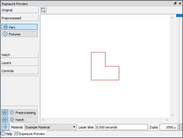
|
|
Intersection Detection, Point Reduction, and Path Offsets
The buildstyle can be found at C:\ProgramData\Autodesk\ATU\ATU-Examples\tutorial-projects\geometry\04_Extra\.
For the most part, this buildstyle is identical to the one above 01_2d-Geometry. It creates a model with ten layers and each layer contains a rectangle.
The new code is added as a new JavaScript file, called demonstration.js. For each layer the demonstration function is called after creating the rectangle. The constructed rectangle and the layer object are passed to the new function.
exports.demonstration = function(layer, rectangle)
{
  var clippingRectangle = new PATH_SET.bsPathSet();
  var cPoint1 = new VEC2.Vec2(0.0, 15.0);
  var cPoint2 = new VEC2.Vec2(0.0,0.0);
  var cPoint3 = new VEC2.Vec2(15.0,0.0);
  var cPoint4 = new VEC2.Vec2(15.0,15.0);

  clippingRectangle.addNewPath(cPoint1,cPoint2,cPoint3,cPoint4);
  clippingRectangle.setClosed(true);

  var result = rectangle.detectIntersection(clippingRectangle);
  process.print('Intersection detected: ' + result);

  layer.addPathSet(rectangle, MODEL.nSubtypePart);

  var path = new PATH_SET.bsPathSet();
  var cPoint1 = new VEC2.Vec2(-15.0,1.0);
  var cPoint2 = new VEC2.Vec2(-15.0,2.0);
  var cPoint3 = new VEC2.Vec2(-15.0,3.0);
  var cPoint4 = new VEC2.Vec2(-15.0,4.0);
  var cPoint5 = new VEC2.Vec2(-15.0,5.0);
  var cPoint6 = new VEC2.Vec2(-15.0,6.0);
  var cPoint7 = new VEC2.Vec2(-15.0,7.0);
  var cPoint8 = new VEC2.Vec2(-15.0,8.0);
  var cPoint9 = new VEC2.Vec2(-15.0,9.0);
  var cPoint0 = new VEC2.Vec2(-15.0,10.0);
  path.addNewPath(cPoint1,cPoint2,cPoint3,cPoint4,cPoint5,cPoint6,cPoint7,cPoint8,cPoint9,cPoint0);

  var removed_points = path.reducePointsInTolerance(0.5, 0.5);
  process.print('Number of removed points: ' + removed_points);

  path.createOffset(0.5);

  layer.addPathSet(path, MODEL.nSubtypeSupport);
};
Functional Description (Step by Step)
A new rectangle is added and the detectIntersection function is used to find an intersection:
var clippingRectangle = new PATH_SET.bsPathSet();
var cPoint1 = new VEC2.Vec2(0.0, 15.0);
var cPoint2 = new VEC2.Vec2(0.0,0.0);
var cPoint3 = new VEC2.Vec2(15.0,0.0);
var cPoint4 = new VEC2.Vec2(15.0,15.0);

clippingRectangle.addNewPath(cPoint1,cPoint2,cPoint3,cPoint4);
clippingRectangle.setClosed(true);

var result = rectangle.detectIntersection(clippingRectangle);
A straight, non-closed polyline is added. This line contains unnecessary points, that will be removed by the reducePointsInTolerance function:
The reducePointsInTolerance function takes two parameters: reducePointsInTolerance and fEdgeLength.
The reducePointsInTolerance parameter defines the maximum deviation of a segment before and after removing a point. The point can be removed only if the deviation is smaller than specified:
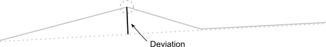
The fEdgeLength parameter removes segments, which are smaller than the specified length.
The units of both parameters are millimeters and the reducePointsInTolerance parameter should be preferred because it produces better results. Points are removed only if one of the two tolerances will be underrun.
var path = new PATH_SET.bsPathSet();
var cPoint1 = new VEC2.Vec2(-15.0,1.0);
var cPoint2 = new VEC2.Vec2(-15.0,2.0);
var cPoint3 = new VEC2.Vec2(-15.0,3.0);
var cPoint4 = new VEC2.Vec2(-15.0,4.0);
var cPoint5 = new VEC2.Vec2(-15.0,5.0);
var cPoint6 = new VEC2.Vec2(-15.0,6.0);
var cPoint7 = new VEC2.Vec2(-15.0,7.0);
var cPoint8 = new VEC2.Vec2(-15.0,8.0);
var cPoint9 = new VEC2.Vec2(-15.0,9.0);
var cPoint0 = new VEC2.Vec2(-15.0,10.0);
path.addNewPath(cPoint1,cPoint2,cPoint3,cPoint4,cPoint5,cPoint6,cPoint7,cPoint8,cPoint9,cPoint0);

var removed_points = path.reducePointsInTolerance(0.5, 0.5);
The last operation creates an offset around the open path and adds the offseted path as a support structure to the layer.
path.createOffset(0.5);
layer.addPathSet(path, MODEL.nSubtypeSupport);
Examine Buildstyle Calculation Results
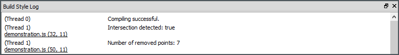
The result of the intersection detection and the number of removed points are outputted to the buildstyle log:
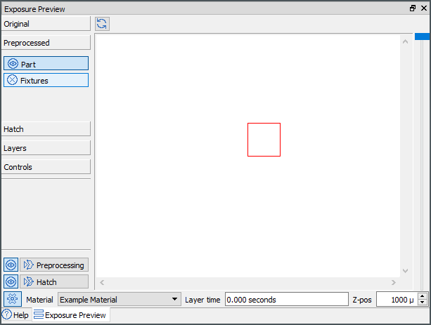
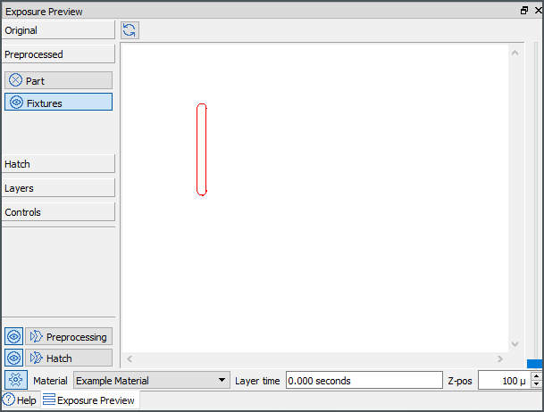
The offset path is displayed at the exposure preview widget:
Test Geometry Buildstyle
The buildstyle can be found at C:\ProgramData\Autodesk\ATU\ATU-Examples\tutorial-projects\geometry\05_Hatch-Geometry\.
For the most part, this buildstyle is identical to the one above (01_2d-Geometry). It creates a model with ten layers and each layer contains a rectangle.
The new code is added as a new JavaScript file, called geometry.js. For each layer, the demonstration function is called. The layer object and the layer index are passed to the new function.
exports.createLayerGeometry = function(layer, layerIdx)
{
  createAMSensitiveStructure1(layer, layerIdx);
  createAMSensitiveStructure2(layer, layerIdx);
  createAMSensitiveStructure3(layer, layerIdx);
  createOpenPath(layer, layerIdx);
  createOffsetedPath(layer, layerIdx);
  createUFO(layer, layerIdx);
  createPyramid(layer, layerIdx);
};
Functional Description
This buildstyle does not use any new operations. It creates test geometry as a preparation for the following tutorial projects.
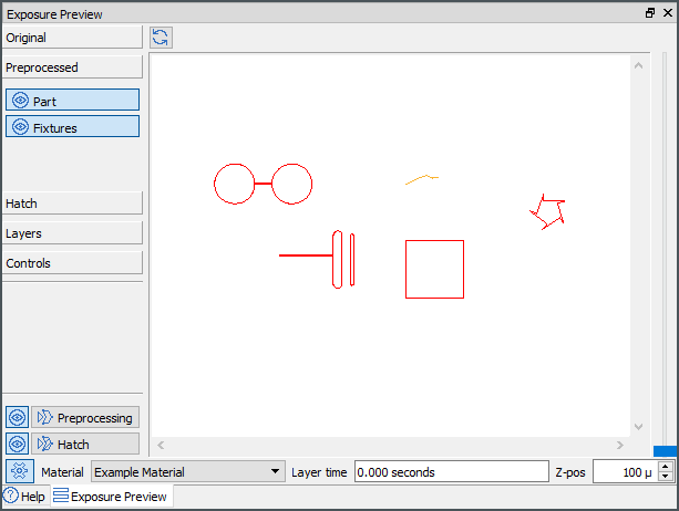
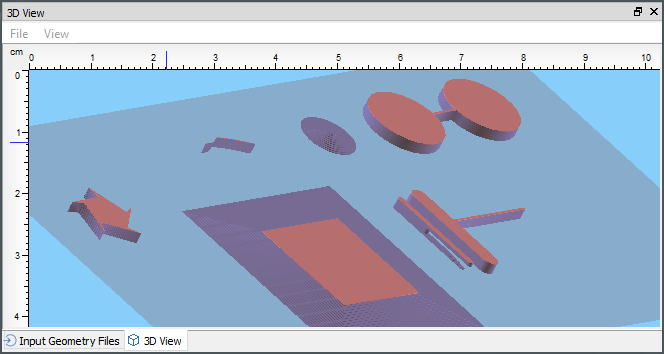
Examine Buildstyle Calculation Results
| Exposure Preview | 3D view |
|---|---|
|
|
In and Outloops
The buildstyle can be found at C:\ProgramData\Autodesk\ATU\ATU-Examples\tutorial-projects\geometry\06_In-Out-Loops\.
For the most part, this buildstyle is identical to the one above (01_2d-Geometry). It creates a model with 10 layers and each layer contains a rectangle.
The new code is added as a new JavaScript file, called geometry.js. For each layer the demonstration function is called. The layer object and the layer index are passed to the new function.
exports.createLayerGeometry = function(layer, layerIdx)
{
exports.createLayerGeometry = function(layer, layerIdx)
{
  var path = new PATH_SET.bsPathSet();
  var points = new Array();

  // counter clock wise (Out-Loop)
  points.push( new VEC2.Vec2(64.90, -3.79));
  points.push( new VEC2.Vec2(62.81,  3.28));
  points.push( new VEC2.Vec2(65.19,  3.90));
  points.push( new VEC2.Vec2(57.81,  4.10));
  points.push( new VEC2.Vec2(57.95,  6.55));
  points.push( new VEC2.Vec2(55.48, -0.39));
  points.push( new VEC2.Vec2(53.19,  0.49));
  points.push( new VEC2.Vec2(59.04, -4.00));
  points.push( new VEC2.Vec2(57.48, -5.89));
  points.push( new VEC2.Vec2(63.57, -1.73));

// clock wise (In-Loop)
//   points.push( new VEC2.Vec2(64.90, -3.79));
//   points.push( new VEC2.Vec2(63.57, -1.73));
//   points.push( new VEC2.Vec2(57.48, -5.89));
//   points.push( new VEC2.Vec2(59.04, -4.00));
//   points.push( new VEC2.Vec2(53.19,  0.49));
//   points.push( new VEC2.Vec2(55.48, -0.39));
//   points.push( new VEC2.Vec2(57.95,  6.55));
//   points.push( new VEC2.Vec2(57.81,  4.10));
//   points.push( new VEC2.Vec2(65.19,  3.90));
//   points.push( new VEC2.Vec2(62.81,  3.28));
//   points.push( new VEC2.Vec2(64.90, -3.79));
  path.addNewPath(points);
  //path.setClosed(true);

  layer.addPathSet(path, MODEL.nSubtypePart);
};
Functional Description (Step by Step)
A path is created with two different point arrays and added to the current layer. The first array contains the points in a clockwise direction the second one in a counterclockwise direction.
Examine Buildstyle Calculation Results
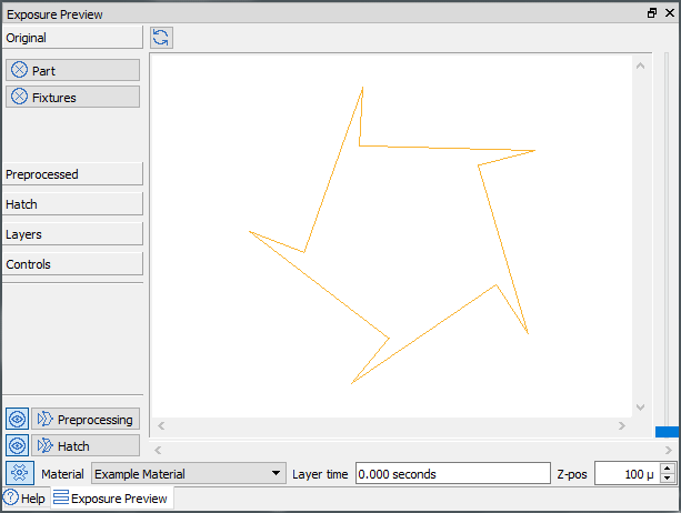
For closed polylines the Advanced Toolpath Utility uses the point direction to differentiate between solid areas and holes. The following example shows a closed area (red) with a few holes inside (blue):
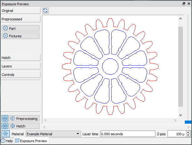
Using the array of clockwise arranged points, the exposure preview widget will be empty, because a hole is constructed without any solid area around it. The counterclockwise oriented point array will show a closed polygon: