
Experimental Build and Measurement
The first step of the calibration process is to manufacture the test part using the material and processing conditions for which a PRM file is desired. Then the peak distortion needs to be measured. This can be achieved using basic metrology equipment such as calipers or a micrometer.
To perform the measurement, use the calipers to determine the diameter at the ’waist’ of the cylinder where the peak displacement occurs. Subtract from the manufactured diameter the nominal width of the test part (12.7mm) and divide by 2 to get the distortion of the printed part:
Measured Distortion = (Measured Diameter – Nominal Diameter)/2
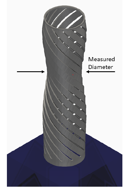
Experimental model and measurement location
For this example, assume the manufactured part is 12.06 mm at the narrowest point:
Measured Distortion = (12.06 mm - 12.7 mm)/2 = –0.32 mm
Input Files
To run a calibration the following files are needed:
- JSON file: This is where the measurement calculated above is entered, along with the measuring device’s error, and points at the thermal and input files. An example calibration file is included in folder 23 of the Local Simulation Example Files.
- Base PRM: This is the starting PRM file. For this example we will be using Inconel625 generic.PRM.
- Thermal and Mechanical input files:
- *PBPF needs to point at the base PRM file.
- *PBPA = 4, if this is set to any other value it will be overridden at execution.
- *PBLR = 0, if this is set to any other value it will be overridden at execution.
- Set Number of Lasers, Dwell Time multiplier, thermal and mechanical boundary conditions to match the experimental set up.
The auto-calibration process is based on measurements taken before heat treatment and while the part is still on the plate, so leave options related to those post processing conditions out of the input files.
Open the calibration.json file. It will look like this:
{
"Calibration":
{
"Thermal input": "t1a.in",
"Mechanical input": "m1a.in",
"Measurement": -0.32,
"Relative error": 5.e-2
}
}
Observe each input file name is specified individually, the measurement has been entered as well as the Relative Error of the calipers. A larger relative error than is typical is used for this example to speed up convergence.
Looking inside the input files you will note that there is no *STLF file. PRM calibration uses an internal version of the flexitube.stl when executed.
Executing the PRM Calibration
To run the calibration process, from a command line run one of the following commands.
Windows:
prm_gen /c calibration.json > calibration.out
Linux and MacOS:
prm_gen -c calibration.json > calibration.out
Users can check the progress of the simulation by viewing the log file, which is recorded to the calibration.out file.