
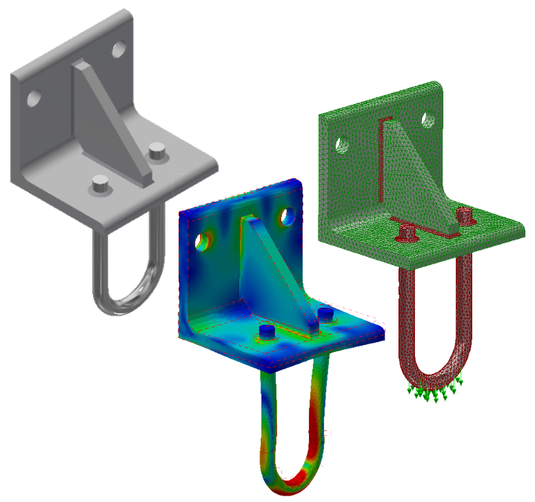
In this tutorial, we complete a linear static stress analysis of a welded steel hanger to which a 6000 N downward load is applied. The weld beads are included in the CAD model as a separate multi-body part so that the stresses in the welds can be determined. Suppress contact between adjacent parts so that only bonding at the part-to-weld interfaces is considered. Fully fix the two mounting hole surfaces in the vertical leg of the angle. Add a constraint against translation in the X-direction to the bottom corner edge of the angle to represent the support of the wall to which the hanger is bolted. The surface of the U-Rod has been split in the CAD model to provide a partial surface for application of the downward force.
Model Dataset
Before starting the tutorial, click this link to download the required model dataset using your web browser. Extract the files to the folder of your choice on your hard drive.
Objectives
- Determine the maximum von Mises stress in the assembly.
- Determine the maximum displacement magnitude.
- Determine the safety factor in the overall model and, specifically, in the welds.
Simulation Data
Materials:
- Angle and Gusset – Steel ASTM A36
- U-Rod and Welds – Steel AISI 1045 225 ANLD (annealed).
Mesh Parameters:
- Continuous Meshing – Disabled
- Size:
- All parts except Welds – 3.7 mm
- Welds – 1.5 mm
Contact:
- Contact Type – Bonded
- Contact generation method – Automatic
- Suppress contact between the Angle and Gusset (these parts are indirectly connected via welds)
Note: At the default contact tolerance of 0.1 mm, contact is not generated between the Angle and U-Rod (due to the rod-to-hole clearance). Therefore, contact suppression between these two parts is not required.
Constraints:
- Cylindrical surface of two holes in the vertical leg of the Angle – Fixed
- Edge along bottom outside corner of the Angle – Tx
Load:
- Force of -6000 N in the Y-direction applied to the top half of the face at the middle of the U-Rod bend
Note: The U-Rod surface has been split to provide a load zone or +/- 45° from bottom dead center of the bend. Additionally, this partial surface has been split along the projected centerline of the rod so that the applied load can be confined to the top half of the U-bend surface.
| Previous Topic: Quick Start Tutorials (introduction) | Next Topic: Open the Model |