
Video Player is loading.
- On the Browser tree, under Idealizations, right-click
Solids
 New.
New.
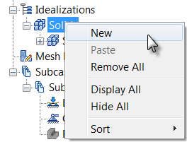
The Idealizations dialog box appears. The default element Type is Solid Elements, which is appropriate for this tutorial model.
- Change the
Name from the default name to
Angle and Gusset.
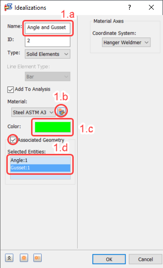
Figure 1.a – 1.d
- Under Material, to the right of the name, click the
New Material button. (See
Figure 1.a – 1.d.) The
Material
dialog box appears.
Consult Figure 1.b.i – 1.b.vi for the following steps.
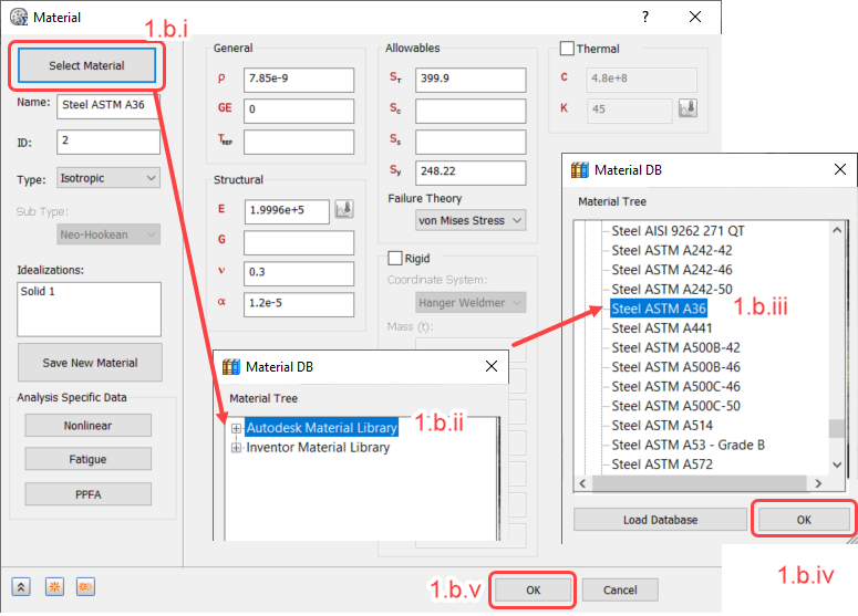
Figure 1.b.i – 1.b.v
- Click Select Material.
- Expand the Autodesk Material Library branch of the Material Tree.
- Scroll down and select
Steel ASTM A36.
Ignore any warning about Failure Theory.
- Click OK to close the Material DB dialog box. In the Material dialog box, ensure that there is no value in the G field (shear modulus). For isotropic materials, G is calculated from the Young's modulus (E) and Poisson's ratio (ν). Deleting the G value prevents a solver warning message caused by a slight discrepancy between the specified and calculated values of G.
- Click OK to close the Material dialog box.
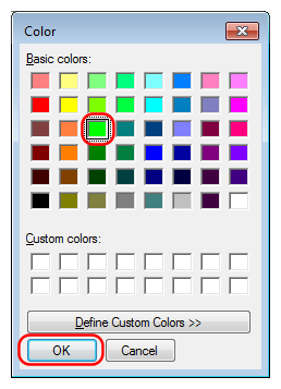
- Click the
Color selection box. (See preceding
Figure 1.a – 1.d.) The
Color
dialog box appears.
- Select the green color in the third row of the third column, as shown in the following image, and click
OK.
- Select the green color in the third row of the third column, as shown in the following image, and click
OK.
- Activate the
Associated Geometry checkbox. (See preceding
Figure 1.a – 1.d.)
- In the model canvas, click the angle and gusset to select them. The part names appear in the
Selected Entities
list and the feature lines of the selected parts turn blue. Be sure that the correct two parts are selected. The ASTM A36 steel material is assigned to these two parts.
- In the model canvas, click the angle and gusset to select them. The part names appear in the
Selected Entities
list and the feature lines of the selected parts turn blue. Be sure that the correct two parts are selected. The ASTM A36 steel material is assigned to these two parts.
- Change the
Name from the default name to
Angle and Gusset.
- Click OK to close the Idealizations dialog box. Angle and Gusset appears in the Idealizations tree.
- In the Idealizations tree, right-click
Solids New.
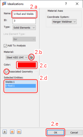
Figure 2 – 2.e
- Change the Name from the default name to U-Rod and Welds. (See Figure 2 – 2.e.)
- Under Material, click the
New Material button. (See
Figure 2 – 2.e.)
(Consult Figure 2.b.i – 2.b.v for the following six steps.)
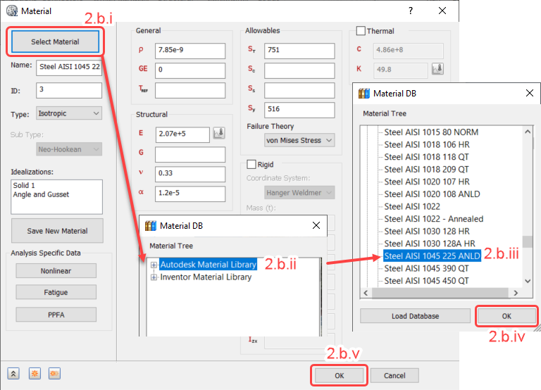
Figure 2.b.i – 2.b.v
- Click Select Material.
- Expand the Autodesk Material Library branch of the Material Tree.
- Scroll down and select
Steel AISI 1045 225 ANLD. (ANLD
is an abbreviation of
annealed.)
Ignore any warnings about Failure Theory.
- Click OK to close the Material DB dialog. Ensure that the G field is blank.
- Click OK to close the Material dialog.
- Click the color selection box. (See
Figure 2 – 2.e.) The
Color
dialog box appears.
- Select the red color in the second row of the first column, as shown in the following image, and click
OK.
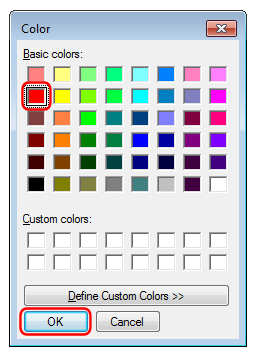
- Select the red color in the second row of the first column, as shown in the following image, and click
OK.
- Activate the
Associated Geometry checkbox. (See
Figure 2 – 2.e.)
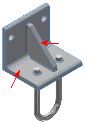
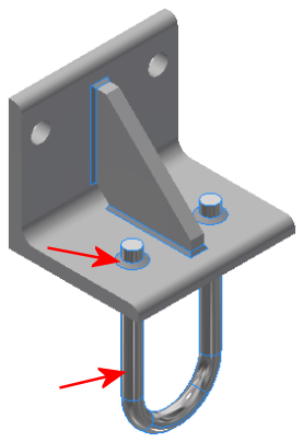
- In the model canvas, click one of the welds and the U-Rod to select them. The part names appear in the
Selected Entities
list and the feature lines of the selected parts turn blue. Be sure that the correct two parts are selected. The AISI 1045 steel material is assigned to these two parts.
- In the model canvas, click one of the welds and the U-Rod to select them. The part names appear in the
Selected Entities
list and the feature lines of the selected parts turn blue. Be sure that the correct two parts are selected. The AISI 1045 steel material is assigned to these two parts.
- Click OK to apply the material, and exit the Idealizations dialog box.
- Verify that you have correctly defined the materials by expanding all browser nodes under
Idealizations. Compare your screen to the following image:
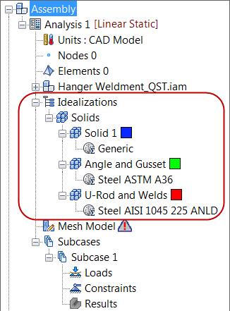 Note: The Generic material definition was imported from the CAD model. However, this material, and the associated element properties, are not assigned to any part of the simulation model (and therefore have no affect on the solution). The CAD material may or may not be imported automatically, depending upon your version of Autodesk Inventor Nastran. So, if you do not see the Solid 1 and Generic nodes in your model browser, there is no need for concern.
| Previous Topic: Open the Model | Next Topic: Mesh the Model |