Define the Material Properties
Create a new material by loading steel from the material library.
- In the Model tree, right-click on Materials and choose New.
- In the dialog, click on Select Material. The Material DB dialog will become populated with the available libraries. Click on Load Database.
- Browse to C:\Program Files\Autodesk\Inventor Nastran 2025\In-CAD\Materials, and open the ADSK_materials.nasmat file.
- The material tree is populated with the available materials. Under the
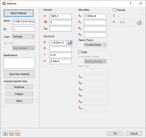
Titanium Alloys category, select
Ti-5Al-2.5 Sn Wrough Cast. Ignore any warning about Failure Theory.
- Click on
 New button. The Titanium Alloy is added to
Materials in the Model tree.
New button. The Titanium Alloy is added to
Materials in the Model tree.
- Click
Select Material, re-open the material library file, click on
Sheet Alloys category, and then select
Sheet Cb+Ti.

- Click the Nonlinear button.
- Select
Elasto-Plastic (Bi-Linear) radio button.
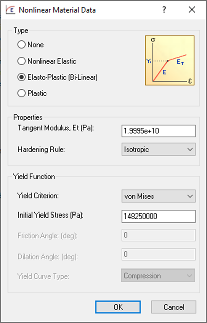
- Accept all the defaults and click OK buttons to create the material.
Define the Element Properties
- In the
Model tree, under
Idealizations, check for any existing definitions under the standard categories, such as
Solids and
Shells. Solid 1, shown below, is an example of an existing definition:
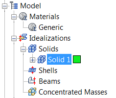
If there are any existing definitions, right-click . Doing this ensures that you won't have unwanted materials appearing in the part mesh and participating in the analysis.
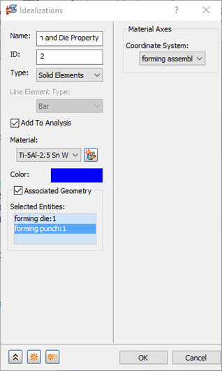
- In the Model tree, right-click on Idealizations and choose New.
- Change the Name to Punch and Die Property.
- Select Solid Elements from the Type drop-down.
- Check Associated Geometry and in the drawing window, select the two curved parts, the forming die and forming punch.
- Make sure
Ti-5Al-2.5 Sn Wrought Cast is selected from the
Material drop-down.
- Click the
New button.
- Name the second property Sheet Slab Property.
- Select Solid Elements from the Type drop-down.
- Check Associated Geometry and in the drawing window, select the forming slab.
- Make sure
Sheet Cb+Ti is selected from the
Material drop-down.
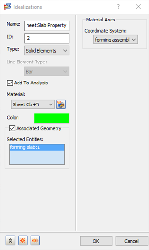
- Click OK to create the physical property.
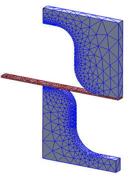
Define the Mesh
- Right-click on Mesh Model and select Edit.
- Enter the Element Size as 0.25 (m).
- Change the Element Order to Linear.
- Uncheck
Continuous Meshing, as the mesh is solid mesh.
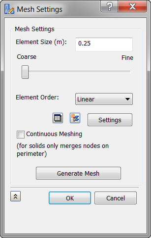
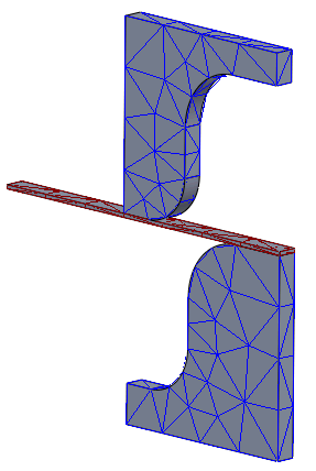
- Click OK to mesh the geometry.
- Notice that the mesh is coarse. To have the proper contact elements between the punch and die with the sheet, you have to create mesh control on edges.
- Right-click Mesh Model and select Add Mesh Control.
- In the
Mesh Control dialog box, click in the
Selected Edges selection box to shift the focus from vertex data, and then select the curved edges on both sides of the punch and die, as shown in the image below.
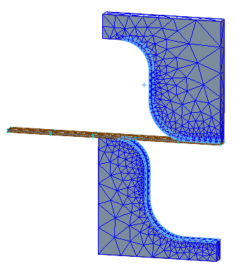
- Under Edge Data, enter 20 for Number of Elements.
- Click on
New button.
- Select the sheet slab's four side edges as shown in the image below.
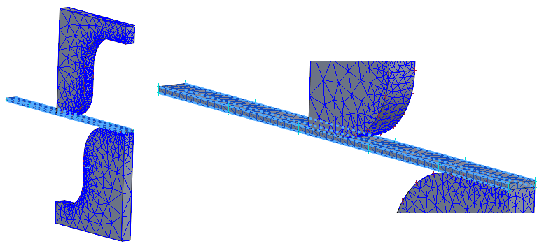
- Enter 50 for Number of Elements.
- Click OK.
- Right-click
Mesh Model and select
Generate Mesh.