
- If it is a big site, mostly all on one level, like a refinery, then look at a site plan and divide it up into areas. Each area may be a process unit, or it may be a logical sub-division of a process unit, but consider it as an AREA.
- In the case of a multi-story plant, you may want to treat each floor as an area and then subdivide into physical areas.
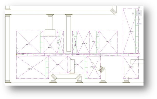
In the middle is a pipe rack which joins up the separate areas (Area 2). This is considered a separate area since we want a designer to be responsible for considering the layout of only the pipes in the rack. Area 13 is a servicing area and contains no 'plant' items (i.e., the models in this area are AEC models, not Plant 3D models) and so there are no P&IDs and no Plant models in this area.
Within each area we have to consider Equipment, Structures and Piping. And if we have different designers focusing on each discipline, we probably want to divide up our areas into the disciplines.
Sample Setup: 14-Area Project
Using the example above we have decided that we will have 14 areas. Each area can managed by a lead designer, but each area has a design team comprising equipment layout designers, Structural layout designers, and piping designers.
In the case of P&ID's we have split the project up into three process areas plus one utilities area which will contain all the Utility P&ID's (or ULD's). The fact that the P&ID area will span several of the Piping areas is not important as Plant 3D will track and manage all the lines and equipment in the project.
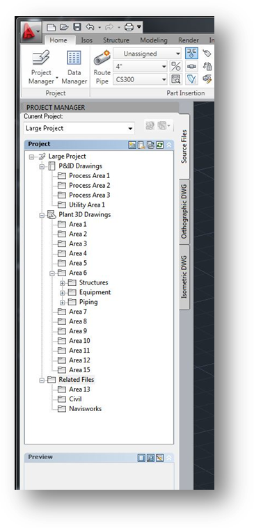
Note that we have 4 P&ID Areas and 13 Piping Areas. We have also allocated folders in 'Related Files'. Here we will store or reference the site plan drawings in the 'Civil' folder. Since Area 13 does not contain any Plant 3D models (it is AEC) we have placed Area 13 in the Related Files section of the project. We also created a Navisworks folder so that we can store the associated .nwf files which will allow us to assign materials to the model files in order to create realistic renderings of the model while we are designing. We can also place the .nwd files here for project review sessions. This allows project reviews to take place while design work proceeds, without interrupting design work.
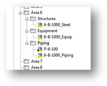
We have created a Structural file in the Structures folder, an Equipment Modeling file in the Equipment folder, and 2 Piping files in the Piping folder.
This structure keeps the file content small and manageable and yet allows maximum flexibility in working in the project. By using Xref's, the designer can focus on the part of the model he is particularly interested in at any moment by unloading the Xref's he doesn't need. Then when he needs more information, simply reload the Xref's for full model realization.