Use the Toolpath Verification dialog to check the Toolpath for collisions or gouges.
Click Home tab > Verification > Toolpath to display the Toolpath Verification dialog.
This dialog contains the following:
Check — Checks the toolpath to see it any part of it collides or gouges.
- Collisions — Checks the toolpath against the tool holder and/or shank. Colliding toolpaths are those where the tool holder or tool shank hit the part.
- Gouges — Checks the toolpath against the cutting portion of the tool. Gouging toolpaths are those where the tool tip hits the part.
Check Against — Checks the toolpath against the model or a stock model.
- Models — Checks the toolpath against the models in the project.
- Stock Model — Checks the toolpath against the selected stock model. You select the stock model from the drop-down list.
Scope — Controls which elements of the toolpath are checked. If the toolpath contains selected components of the type specified, then only that set of selected components are checked. For example, if the scope is set to Links, and if some of the links within the toolpath are selected, only the selected links are verified.
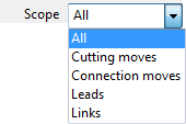
- All — All the toolpath components are checked.
- Cutting Moves — The toolpath cutting moves are checked.
- Connection Moves — The toolpath leads and links are checked.
- Leads — The toolpath leads are checked.
- Links — The toolpath links are checked.
When selecting All, if collisions or gouges are found, the toolpath is split at segment ends. The toolpath is not split into its component parts. The Information dialog identifies the toolpath components that collide or gouge.
Split Toolpath — Determines how the toolpath is split into its safe and unsafe portions.
- Output Safe Moves — Creates a toolpath containing the portions of the toolpath that miss the model.
- Output Unsafe Moves — Creates a toolpath containing the portions of the toolpath that hit the model.
- Reorder Toolpaths
— Reorders the toolpaths to minimise the 3D distance between the ends of segments whilst maintaining the cutting direction of segments.
When gouge-checking against a stock model, the useful moves are those which gouge the stock model, as they are the ones that actually cut something.
- Split Moves — When selected, splits individual moves (for example, individual segments, leads, links…) into their safe and unsafe portions. When deselected, the entire move is added to the unsafe toolpath if any portion of it is unsafe.
- Overlap — The amount by which an unsafe move is extended to overlap with an adjacent safe move. This reduces surface marks where clear and colliding toolpaths meet.
- Minimum Length — The minimum length required for the safe portion of an unsafe move to be kept on the safe toolpath. For example, if part of a segment is unsafe, but the SAFE portion is shorter than this minimum length then it too is added to the unsafe toolpath.
Head clearance — Enter the length of the tool tip, shank, and holder combined. If the height of the tool assembly is less than the Head clearance, an additional component is added to the tool assembly. This additional component has the same diameter as the uppermost item in the tool assembly (if Automatic collision checking is On), and a length so that the specified total tool-assembly length is the same as the Head clearance.
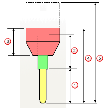
 Tool length
 Shank length
 Holder length
 Minimum head clearance value
 If a head clearance value is greater than the tool assembly height, then an additional component is added.
- The height of the tool assembly is just the cutter (
 ) if
Automatic collision checking is
Off
and is the tip, shank, and holder (
 ) if
Automatic collision checking
is
On.
- If you define a tool assembly which is longer than the Head clearance value, then the Head clearance value is ignored.
- For disc cutters, if a shank is defined, then additional components are added to give the total tool assembly a length equal to the Head clearance value.
Verification Thickness — Applies a different thickness when verifying the toolpath to the thickness used when generating it.
 Thickness — Enter the amount of material to be left on the part. Click the
Thickness
 button to separate the
Thickness box into
Radial thickness
 and
Axial thickness
 . Use these to specify separate Radial and Axial thickness as independent values. Separate
Radial and
Axial
thickness values are useful for orthogonal parts. You can use independent thickness on sloping walled parts, although it is more difficult to predict the results.
 Radial thickness — Enter the radial offset to the tool. When 2.5-axis or 3-axis machining, a positive value leaves material on vertical walls.
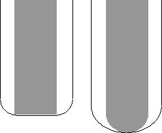
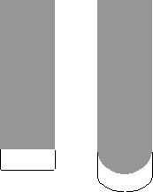
 Axial thickness — Enter the offset to the tool, in the tool axis direction only. When 2.5-axis or 3-axis machining, a positive value leaves material on horizontal faces.
 — Displays the
Verification Thickness dialog which enables you to specify the thicknesses of the different surfaces.
Collision Options — Options which are only relevant to collision checking.
- Replace Tool — Select a tool to replace the tool used to create the toolpath with one with the same tip definition, but a differing shank and holder definition. This enables you to calculate the toolpath with just the tip specified and then collision check it against a tool with the tool shank and tool holder specified.
If a tool is locked by only one toolpath, then that tool holder can be modified during the collision checking process. If a tool is locked by more than one toolpath then it is not possible to modify the tool holder. The way around this is to copy the tool profile. Do this by selecting Settings from the individual tool context menu and click
 . The tool used in the active toolpath is then replaced by this copy. Since this tool is now locked by only one toolpath, then the tool holder can be modified during the collision checking process.
- Shank Clearance — Enter the “safe” distance around the tool shank which is taken into account when checking for collisions.
- Holder Clearance — Enter the “safe” distance around the tool holder which is taken into account when checking for collisions.
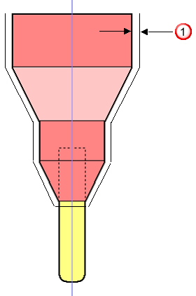
When the clearance area gouges into the job, the collision is detected and the depth of gouge is displayed. To determine whether it is safe to proceed, compare the gouge depth with the clearance value. For example, a tool produces a 2mm gouge when using a 15mm clearance: whether it is safe to continue depends on the thickness left by preceding toolpaths.
- Calculate Collision Depth — Select to determine the collision depth, if a collision occurs. When deselected, this determines whether the toolpath collides or not but does not determine the depth of the collision.
- Adjust Tool — Select to enable PowerMill to modify the properties (overhang, cutting length) of the tool to avoid collisions. This takes into account the collision depth required to make the toolpath safe.
- Adjust overhang only — Select to enable PowerMill to modify the holder overhang, to avoid holder collisions, without modifying the shank. Therefore, shank collisions may still occur. This is useful when you want to correct holder collisions but not shank collisions.
- Always Create New Tool — Select to always create a tool when a collision occurs. The new tool's properties (overhang, cutting length, collision depth) does result in collisions for the specified toolpath.
Draw Unsafe Moves — When this box is selected, colliding moves in the toolpath are highlighted.
Apply — Automatically highlights any areas where gouging occurs (colliding toolpaths are shown in red). It also displays the depth of the gouge, and the tool overhang required to prevent gouging.