
Use this dialog to create a stepped split surface.
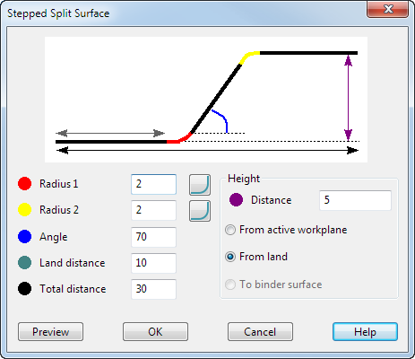 Colour coding has been used alongside the labels to help identify the values.
Radius 1 — Enter a value for the angle of the first radius.
Radius 2 — Enter a value for the angle of the second radius.
If you enter zero radii in the Stepped Split Surface dialog, the result is a sharp discontinuity with no fillet. This is needed in some complex cases where the fillet may need to be added manually later.
 — Toggle between chamfered or filleted edges. The corners of the step can be either filleted or chamfered. The option can be set independently for
Radius 1 and
Radius 2.
— Toggle between chamfered or filleted edges. The corners of the step can be either filleted or chamfered. The option can be set independently for
Radius 1 and
Radius 2.
Angle — Enter a value for the draft angle.
Land distance — The initial flat split distance.
Total distance — This value indicates the total extent of the stepped split surface.
Height
Distance — Height of the step. This value can be specified in three ways:
- From active workplane — The height is the distance along the principal axis from the principal plane in the current workplane. This option means that the run-off part of the surface (the bit after the step) is always planar.
- From land — The run off is an offset continuation of the land and follows the 3D shape of the original split line.
- To Binder surface — This option is active when you select a binder surface. The value entered for
Distance is ignored. The step is effectively a draft onto the binder surface that is then filleted/chamfered back.
Preview — View the stepped split surface.
OK — Accept the values and close the dialog.
Cancel — Return to the Split Surface dialog. As the direction of the laterals in the stepped split are identical to those in the basic split, it is useful to be able to return to the Split Surface dialog to change the Split Direction or to use the Advanced options before returning to the Stepped Split Surface page.