
The parameters of the seismic simplified analysis according to the equivalent lateral force method depend on a seismic code and a method of defining values of the fundamental periods selected in the Seismic Analysis dialog.
Access
- Click
Tools
 Job Preferences Design Codes.
- Go to the Loads section, and then select ASCE 7-22 from the seismic loads menu.
- Click
AnalysisAnalysis Types.
The Analysis Types dialog displays.
- Click
New.
The New Case Definition dialog opens.
- Select
Seismic (Equivalent Lateral Force Method), and click
OK.
The Seismic Analysis dialog opens.
- Click
Seismic Analysis Parameters.
The Parameters dialog opens.
Dialog elements
Fundamental period (Ta)
The parameters of the seismic simplified analysis according to the equivalent lateral force method depend on a seismic code and a method of defining the values of the fundamental periods selected in the Seismic Analysis dialog.
- Approximate (according to the seismic code)
- User-defined value in seconds
- Precise (using oscillation period based on modal analysis)
You can define the following structure types in each direction independently:
- Bare MRF buildings (without any masonry infills)
-
- RC MRF buildings
- RC-Steel Composite MRF buildings
- Steel MRF buildings
- Buildings with RC structural walls
- Other buildings
Approximate method
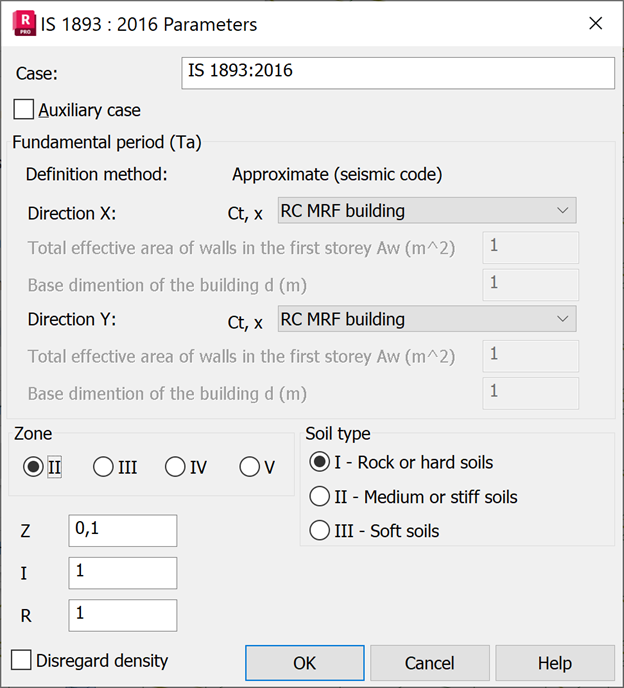
The approximate fundamental natural period Ta is calculated according to the IS 1893 (Part 1):2016, clause 7.6.2 depending on the selected structure type:
- · RC MRF buildings Ta = 0.075 * h 0.75
- RC-Steel Composite MRF buildings: Ta = 0.085 * h 0.75
- Steel MRF buildings: Ta = 0.085 * h 0.75
- Buildings with RC structural walls: Ta = 0.075 * h 0.75 / √Aw
- Other buildings: Ta = 0.09 * h 0.75 / √d
where:
h - structure height (m), defined automatically by difference between Structure range and Reference level
d - base dimension (m) of the building at the plinth level along the considered direction of earthquake
Aw - total effective area (m2) of walls in the first story of the building according to clause 7.6.2 (b)
User defined
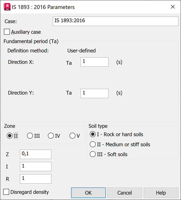
The fundamental period Ta values are entered manually by the user in each X and Y direction.
Precise method
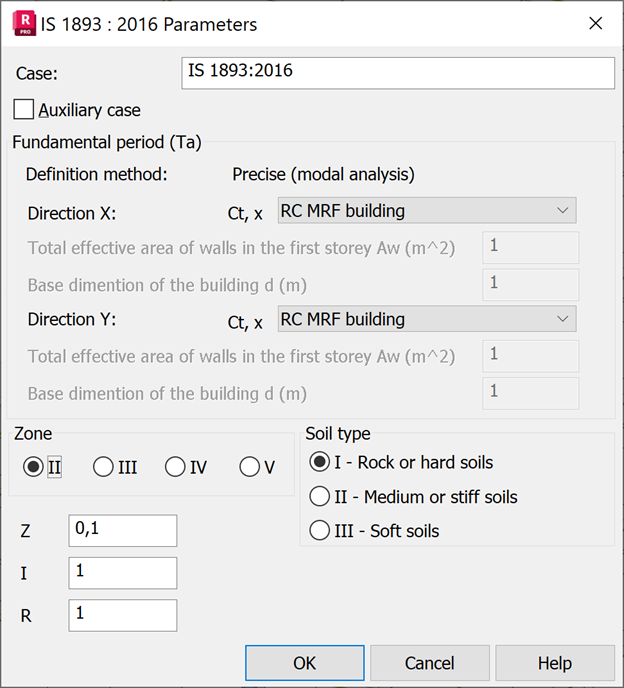
In this method a modal analysis case is created. Fundamental period is calculated for both X and Y directions.
If the option "Periods with maximal mass participation" is off in the Seismic Analysis dialog, then the first mode in direction where are participating masses is taken as fundamental period.
If this option is on, fundamental period is taken from the mode, which fulfill limitations and gives the maximum participating masses in the direction.
Please pay attention that the fundamental period calculated with modal analysis may be different from Ta estimated by IS 1893 (Part 1):2016, clause 7.6.2. So, the calculated base shear may be smaller if the calculated period is greater than the estimated one.
Code parameters
To complete the seismic analysis according to the rules given in this code, define the following parameters:
- Z - Seismic zone factor,
given in IS 1893 (Parts 1 to 5), clause 6.4.2 Table 3, the value is assigned according to the choice of seismic zone. For determining design seismic force, the country is classified into four seismic zones (II, II, IV, V) as shown in Figure 1.
- I - Seismic Importance Factor,
given in IS 1893 (Parts 1 to 5), clause 7.2.3 Table 8, the minimum value shall be:
- 1.5 for critical and lifeline structures,
- 1.2 for business continuity structures,
- 1.0 for the rest
- R - Response reduction factor,
given in IS 1893 (Parts 1 to 5) for the corresponding structures, clause 7.2.6 Table 9
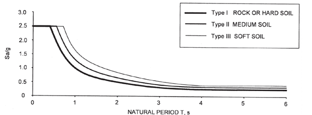
- Site soil class
For determining the correct spectrum to be used, the type of soil on which the structure is placed shall be identified by the classification given in Table 4 clause 6.3.5.2, as:
- Soil type I - Rock or hard soil,
- Soil type II - Medium and stiff soil,
- Soil type III - Soft soil,
- ·Spectrum for equivalent static method
The design horizontal seismic acceleration coefficient Ah is determined for the estimated fundamental frequency Ta, based on the above factors, according to the formula 6.4.2 expression (a).
Base shear
Finally, the design Base Shear force VB in the direction of concern is calculated according to the formula 7.6.1:
VB = Ah *W
where Ah is the horizontal seismic acceleration coefficient according to 6.4.2, based on the estimated fundamental period Ta,
and W is the effective seismic weight of the structure as per 7.4. The effective seismic weight of each story is calculated based on the self-weight of the structural elements, as well as added masses and loads converted to masses.
The total design lateral base shear VB is distributed to each level Qi following expression:
Qi = VB * Wi *h i 2 / ( Σ j n Wj * hj 2)where
Wi - Portion of the total effective seismic weight of the structure (W) located or assigned to level i
hi - height from base level to appropriate floor level i
n - number of stories in the building, it is the number of levels at which masses are located
Regardless of estimated VB Base Share value, the minimum lateral force takes into account the value (VB)min according to 7.2.2, calculated as W multiplied by ρ percentage value given in Table 7 for the relevant Seismic Zone.
Disregard density
Excludes the density of the structure element (ρ=0) during the estimation of effective seismic weight applied to the stories of the structural model during analysis.
In this case you need to apply added masses or loads conversion to masses as defined in Load Types dialog at Load to Mass Conversion tab.
You can examine all the input parameters and base shear force distribution in the Calculation Notes (open Analysis > Calculation Notes > Simplified/Full Note)