
RC walls are calculated according to the principles given in:
- NF EN 1992-1-1/NA:2007 (NF P 18-711-1)
- 'Recommandations professionnelles pour l'application de la norme NF EN 1992-1-1 (NF P 18-711-1)'
- EN 1992-1-1/AC:2008
CALCULATION METHOD
The wall design is based on the assumption that the wall works in its plane as an RC section. Parabolic-linear distribution of compressive stresses in the section is adopted here.
Calculations are performed for an unreinforced wall and, if needed, for one with reinforcement. The design process is focused on the bottom section of the wall.
The calculation algorithm is as follows.
- For load reduction, linear loads are reduced to the system N - M - V.
- For calculations of the load capacity of an unreinforced wall, refer to the descriptions of algorithms of wall calculations.
- If load capacity of an unreinforced wall is less than the impact due to the vertical reduced forces N, then uniform reinforcement distribution is assumed.
- Based on distributed reinforcement (the greater of individual seismic and non-seismic combinations is adopted), load capacity of a reinforced wall is calculated (separately for seismic and non-seismic structures).
- If mean compressing stress in the wall or mean stress on compression strap exceeds the allowable stress in concrete, calculations are interrupted. Dimensions of the wall section should be increased.
- Calculations of compression with bending are performed, assuming the section resistance from concrete strength or concrete with distributed reinforcement, taking into account wall buckling (the a coefficient)
- Reinforcement for compression with bending is arranged near wall edges (with hidden zones). Distributed vertical reinforcement is calculated to be able to carry the N force and possible reinforcement resulting from the verification of shear and sliding. Both are generated along the whole section.
The algorithm of wall calculations (non-seismic loads)
The basic dimensions of walls are presented in the following drawing.
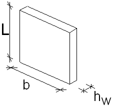
It is assumed that:
- wall length b ≥ 4 · hw
- wall thickness:
a ≥ 10 cm are internal walls (and external, but according to EN all not reinforced walls should have ≥ 12 cm, and user can choose in calculation options whether it is internal or external wall
a ≥ 12 cm are external walls
- slenderness λ ≤ 86
Individual steps of the calculation algorithm for walls subjected to non-seismic loads are as follows:
- Calculations of b according to Tab 12.1 (EN 1992-1-1/AC:2008)
- Calculation of a buckling length of a wall l0, where l0= β · lw
- Calculation of slenderness λ, where λ=l0/i
- The load capacity condition of the wall is checked for the bottom level of the wall. Load capacity of the wall section is checked for reduced vertical loads, and reinforcement is distributed uniformly in the whole section. In subsequent steps of calculations, load capacity of a reinforced or unreinforced wall, is respectively taken into account.
- Verification of load capacity of the unreinforced wall section is checked for the mean compressing stress or mean stress on compressed strap
σ moy =N/(b · hw) ≤ σ ulim
σ band,moy =N/(b · hw) ≤ σ ulim
If mean compressing stress in the wall or mean stress on compression strap exceeds the allowable stress in concrete, calculations are interrupted. Dimensions of the wall section should be increased.
- Calculation of the load capacity of unreinforced wall N ulim and the allowable stress σ ulim
Φ = min(1-2 · etot/hw; 1.14(1-2 · etot/hw) - 0.02 · l0/hw )
Where etot=e0+ei
Nulim= b · hw · fcd,pl · Φ
σ ulim = Nulim/(b · hw)
If Numax ≥ Nulim then reinforcement for compression with bending will be arranged near wall edges
- Generation of reinforcement distributed in the wall
The minimum ratio of the vertical reinforcement must equal:
As,vmin = 0,002 · Ac
The maximum ratio of the vertical reinforcement must equal:
As,vmax = 0,04 · Ac
The distance between two adjacent bars should not exceed 3 · hw and 400mm
The horizontal reinforcement fulfills the conditions:
(the reinforcement is distributed uniformly along the wall height)
As,hmin = max (25%Av; 0,001 · Ac)
The distance between two adjacent bars should not exceed 400mm
- Calculations and generation of edge reinforcement
As indicated in the assumptions of the method, calculations of this reinforcement are focused on ensuring that bending with compression can be carried by a structure; it is generated in a 'hidden zone' of the width equal to d'.
- Calculations of shear capacity of unreinforced wall
σ cp = N/(hw · b)
t cp = k · V/(hw · b)
σ c,lim = fcd - 2 · (fctd · (fctd+fcd)) ½
If σ cp ≤ σ c,lim :
fcvd= (fctd,pl 2 + σ cp · fctd,pl 2 ) ½
If σ cp > σ c,lim :
fcvd= (fctd,pl 2+ σ cp·fctd,pl2 - 0,25 · ( σ cp - σ c,lim )2) ½
- Shear verification for unreinforced wall
If τ cp <= fcvd then shear reinforcement calculated on the basis of following criterions must be distributed uniformly along the wall length :
vmin = 0.35/ γ c · fck ½
k = min(1+(200/b) ½ ); 2)
CRd,c =0.18/ γ c
σ cp =min(0,2 · fcd; N/(hw · b))
VRd,c = max((CRd,c · k · (100 · ρl · fck) (1/3)+k1 · σcp )*hw*d; (vmin+ k1 · σcp ) · hw · d) (1/3))
- Shear verification for reinforced wall
Vertical ULS loads must meet the following criterion:
V<=VRd,c
- Generation of the anti-shrinkage and constructional reinforcements.
Anti-shrinkage reinforcement:
= vertical
= horizontal
