
See the additional calculations for beam supports, using the struts-and-tie method, based on the French annex NF EN 1992-1-1 / NA:2016.
Assumptions:
- This functionality is available only for the beams in the provided reinforcement module.
- It based on NF EN 1992-1-1/NA:2016.
- The calculations are applied to paragraph 9.2.1.4(2) and formulas (9.101NF), (9.102NF), (9.103NF), (9.104NF) and 9.2.1.5 (9.105NF).
- In range of this module it is to check compressive stresses in struts and to calculate the required reinforcement needed to carry tension loads in the bottom part of the beam.
- In case of exceeding maximum compressive stress in struts, additional reinforcement is designed. This solution enables carrying extra loads. It increases the maximum value of compressive stress that can be sustained by struts, but it changes the geometry of these elements.
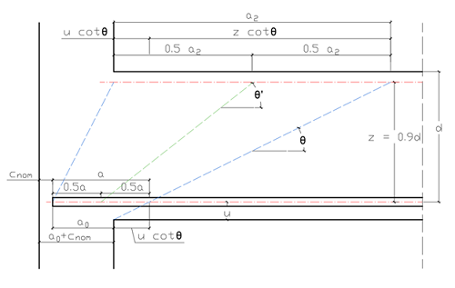
- Dimension z, based on 6.2.3(1), is equal to 0.9*d (z=0.9*d).
Beam Result Note
- In Project: Building Design, click
 (Provided Reinforcement of RC Elements).
- In the
Beam-note tab you can check the formulas used in these modules. Moreover, for each support, intermediate results are displayed here.

Description of variables:
VEd - shear force close to support.
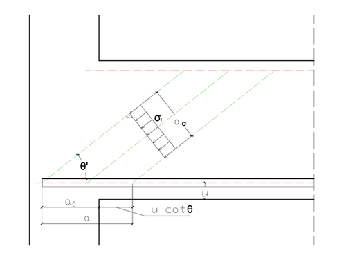
aσ - width of the struts.
a - length of the base of the strut (look at the picture above).
σRd.max - the design strength for a concrete strut.
σEd = σ1 - the value of the compressive stress in the strut.
FcEd - the compression force carried by the concrete strut.
FtEd - tensile force carried by steel.
Δ As.req - additional required reinforcement.
As.prov - total provided reinforcement.
As.prov ≥ Δ As.req
To display additional reinforcement at the figure, open the Beam-diagrams tab and below the table set Switch to: reinforcement.
There will be an attempt to create an additional strut above the exiting one if the maximum compressive stress in the primary struts is exceeded (marked in the picture as A-B-C-D).
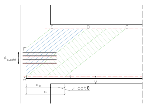
To construct this element, it is required to design additional horizontal reinforcement. Its main goal is to carry tension loads.
The angle of the new compression strut is marked as θ' and its maximum dimension is determined by the distance between points D and E.
If design strength for a primary concrete strut is exceeded, then the assumption is that this element sustains the maximum acceptable force and extra loads are carried by the newly created strut.
- It must allow the arrangement of the additional horizontal reinforcement.
- The value of the comprehensive stress in the new strut must be less than maximum.
Additional assumption: the minimum dimension of the strut must be equal to or greater than 5 cm.