
The Configuration dialog box is used to define parameters applied in verification of a steel member (the Japanese steel code). The dialog box opens on pressing the Configuration button in the Calculations dialog box. The dialog box shown below appears on screen then.
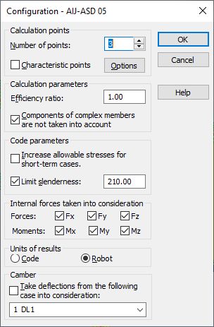
The following calculation parameters may be defined in the above dialog box:
- calculation points; they can be determined in two ways:
= by defining a number of points along the member length (the points are evenly distributed along the member length) - the Number of points option
= by defining coordinates of the characteristic points; to do it, switch on the Characteristic points option and press the Options button; it opens the Calculations in Characteristic Points dialog box
- efficiency ratio determines the factor by which the design steel strength will be multiplied (increasing/decreasing the design strength).
If the Components of complex bars are not taken into account option is switched on, then the program will not take account of components of these bars during calculations of complex bars.
In the middle part of the dialog box are the options that enable definition of the following code parameters:
- Increase allowable stresses for short-term cases - if this option is switched on, then allowable stresses for short-term loads are increased according to the principles given in point 5.6 of the code The program does not recognize automatically if cases defined for calculations are short-term ones. This is the user who decides which load cases should be selected
- Limit slenderness; if this option is switched on, the check of member slenderness is performed; in the edit field the user may change a default slenderness value according to section 11.2 of the code.
In the middle part of the dialog box, it is also possible to choose internal forces to be taken into account in member code calculations; switching on an option (e.g. Fx) results in the Fx force being considered in calculations. Moreover, units for presentation of results of the member design may be selected here. The results may be presented in the units used in the Japanese steel code, or in the units applied in the Robot program.
The lower part of the dialog box holds the list for selection of a load case (dead load), for which the displacements calculated will be treated as structure camber. The option Take the deflections from the following case into consideration must be switched on then.