
This dialog defines buckling parameters (buckling scheme) for a designed RC column. Access the dialog, by clicking the Column tab on the RC Member Type Definition dialog, and selecting the icon that denotes the bucking scheme.
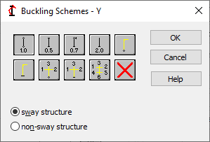
The buckling length coefficient is entered automatically once one of the icons with the appropriate end support conditions is selected.
The icons are divided into two groups:
- The first group contains typical (codified) methods of member support and corresponding values of buckling coefficients,
- The second group contains icons of options used for calculating the buckling coefficient for columns of multi-story frames (calculation of the buckling length coefficient for one, three and six adjoining bars). Double-clicking one of the icons standing for calculation of the buckling length coefficient (,
 ,
,  ,
,  ,
,  ,
,  ) results in opening an additional dialog.
Buckling is considered in calculations when a compression force appears in the member, even if it is negligible in comparison to other internal forces. A separate analysis is not performed to determine if buckling effects may be disregarded or not. To eliminate buckling effects from the calculations, click ![]() . If selected, buckling will be disregarded in the calculation process.
. If selected, buckling will be disregarded in the calculation process.
For several codes the ![]() icon appears in the dialog. Clicking this icon indicates that calculations of the buckling length of a column will be performed according to the automatic procedure (see: Automatic buckling length).
icon appears in the dialog. Clicking this icon indicates that calculations of the buckling length of a column will be performed according to the automatic procedure (see: Automatic buckling length).