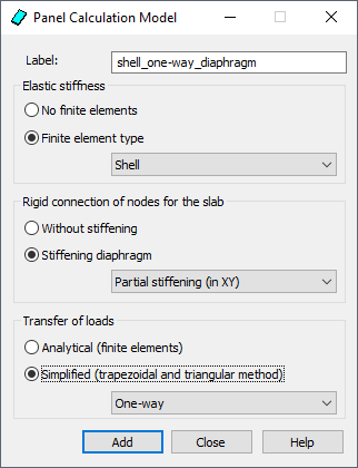
Use the option to define a new panel calculation model. Access the option clicking New panel calculation model in the Panel Calculation Model dialog. The following dialog displays then.

A panel calculation model defines the way you reach a solution for displacements, internal forces and supporting objects of a panel. A set of parameters that characterize a calculation model includes 3 groups:
- Elastic stiffness - select whether finite elements are used (if so, what type of FEs is used)
- Rigid connection of nodes for the slab - specify whether displacements are additionally diaphragm-stiffened
- Transfer of loads - specify how loads are distributed on the adjoining elements: based on finite elements or using trapezoidal and triangular method.
You can specify the following parameters in the above dialog:
- finite element type
- No finite elements - finite elements are not generated while a model is being generated; Robot only generates a cladding with material parameters that are assigned by a specified thickness
- Finite element type (membrane, shell or slab) - elements with different degrees of freedom are used for different structure types (Slab, Shell, PSO, PSO, AXI)
To distinguish a panel with a finite element mesh from a panel on which this mesh is not generated, a panel contour is drawn differently: panel with a FE mesh is drawn with a dashed line and panel without an FE mesh - with a continuous line.
- Rigid connection of nodes for the slab (diaphragm type for slabs)
- Without stiffening - a diaphragm is not generated
- Stiffening diaphragm:
Full stiffening (rigid body) - an object that assigns to all nodes in the plane and in the panel contour a rigid body connection (all degrees of freedom are fixed)
Flexible stiffening (in XY) - an object that assigns to all nodes in the plane and in the panel contour a rigid membrane connection (the UX, UY, RZ degrees of freedom are fixed
- Transfer of loads
- Analytical method (finite elements) - it is a standard solution based on generating a finite element mesh and distributing loads on nodes of this mesh
- Simplified (trapezoidal and triangular method) - loads are distributed using the trapezoidal and triangular method; 2 options are available:
One-way - distribution in one direction based on the trapezoidal and triangular method; the direction of distributing the loads is associated with the local coordinate system of a panel and the load direction is associated with the X axis of the local coordinate system of a panel
Two-way - distribution in two directions based on the trapezoidal and triangular method.
