
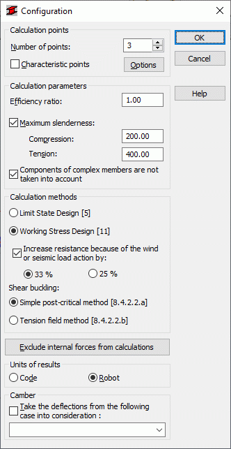
The Configuration dialog defines parameters used during the verification of a steel member. Access the dialog clicking the Configuration button in the Calculations dialog. The following dialog displays:
You can specify the following calculation parameters:
- Calculation points. You can define them 2 ways:
- Specify a number of points along the member length (the points are evenly distributed along the member length) in the Number of points field
- Specify coordinates of characteristic points. Access this option by selecting Characteristic points, and click the Options button to open the Calculations in Characteristic Points dialog.
- Efficiency ratio: defines the coefficient by which to multiply the plasticity limit (to increase or decrease the plasticity limit).
- Maximum slenderness; when selected, Robot checks the member slenderness - it applies to compression members and tension members.
If you selected the Components of Complex Bars are not taken into account option, Robot ignores components of complex bars during calculations of these bars.
You can use either of the following methods to perform calculations according to the code:
- Limit State Design
- Working Stress Design.
You can use the following alternative verification methods:
- Simple post-critical method - after you select it, Robot verifies a member according to Section 8.4.2.2.a.
- Tension field method - after you select it, Robot verifies a member according to Section 8.4.2.2.b.
Selecting the Increase resistance because of the wind or seismic load action by option, you can increase (according to Section 11.1.4 of the code) the calculated allowable resistance values by 33 or 25 percent, for load combinations including wind and seismic cases. You can use this option only if you selected the Working Stress Design [11] method.
In the middle of the dialog is the Exclude internal forces from calculations button; click it to open the Internal forces not taken into consideration dialog; use this dialog box to specify the limit values of internal forces (thus you can ignore force values that are 'negligible' for a given section). Also, you can select units for displaying results of the member design. You can use units from a selected steel code or Robot units.
At the bottom of the dialog is a list for selecting a load case (dead load); Robot treats calculated displacements as structure initial deflections. You must select the Take the deflections from the following case into consideration option then.