
Use the Cut Profile tool to change the shape of elements that are cut in a view, such as roofs, floors, walls, and the layers of compound structures.
The tool is available in plan, RCP, and section views. Changes made to the profile are view-specific; that is, the element's 3D geometry and its appearance in other views does not change.
 Video: Change the Cut Profile of Elements
- Click View tab
 Graphics panel
 (Cut Profile).
- On the Options Bar, for Edit, select Face (to edit the entire boundary around the face) or Boundary between faces (to edit the boundary line between faces).
- Move the cursor over an element in the view (for example, a compound wall).
Depending on the selected Edit option, a valid cut face or a boundary line is highlighted.
- Click the highlighted cut face or boundary to select it and enter sketch mode.
-
Sketch an area to be added to or subtracted from the selection. Use a sequence of lines that starts and ends at the same boundary line.
You cannot sketch a closed loop or cross the starting boundary line. However, if you are using the Boundary Between Faces option, you can sketch over other boundaries of the face.
A control arrow displays on the first line that you sketch. It points toward the portion that will remain after editing. Click the control arrow to change its direction.
Note: When you are editing a boundary line between faces, you only need to sketch the 2 boundary lines for the area. A connecting line displays between the 2 lines that you sketch. You do not need to sketch this line. - When finished editing, click
 (Finish Edit Mode).
- To change the graphic display (such as line weight or color) of elements in the view, right-click the element, and click Override Graphics in ViewBy Element. See
Override Visibility and Graphic Display of Individual Elements.
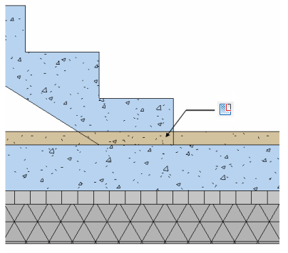
When you have 2 adjoining elements and you want to edit the profile as shown below, use the Boundary Between Faces option to achieve the desired effect.