
Use fill patterns to define the appearance of surfaces that are cut or shown in projection.
 Video: Create a Fill Pattern
When defining a surface pattern or a cut pattern to use in the model, you can specify different fill patterns and colors for the foreground and background.
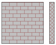
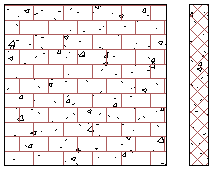
| Brick wall | Concrete block wall |
|---|---|
| In an elevation, the surface pattern of the wall uses the block fill pattern drawn in red over a solid gray background. In a section view, the wall's cut pattern uses the diagonal crosshatch fill pattern drawn in red over a solid gray background. | In an elevation, the surface pattern of the wall uses the block fill pattern drawn in red over a concrete fill background draw in black. In a section view, the wall's cut pattern uses the diagonal crosshatch fill pattern drawn in red over a concrete fill background draw in black. |
 |
 |
Creating and managing fill patterns
Revit LT includes several fill patterns and stores them in the default project template file. Alternatively, you can create your own or edit an existing fill pattern to meet your needs. Click Manage tab Settings panelAdditional Settings drop-downFill Patterns.
A fill pattern is stored in the project file in which it was created. To save the pattern to a project template, open the template file and create the pattern there.
You can transfer fill patterns between projects using the Transfer Project Standards tool.
Using fill patterns for surface patterns and cut patterns
Use fill patterns to define the surface patterns and cut patterns for the graphic representation of elements in the model. For each surface pattern and cut pattern, you can specify one fill pattern and color for the foreground, and another fill pattern and color for the background. (For examples, see the table above.) Use these patterns to distinguish elements visually in views, improve the readability of project documentation, and meet office or industry standards.
You can specify surface patterns and cut patterns in several ways:
- Materials. To specify fill patterns for the graphics used to represent materials for model elements in views, use the Materials Browser. See Change the Graphics Properties of a Material. To assign materials to elements, see Apply Materials to Elements.
- Graphic overrides for an element. In a view, you can change the surface pattern and the cut pattern for an individual element.
- Graphic overrides for a model category or a filter. In a view, use the Visibility/Graphic Overrides dialog to change the surface pattern and the cut pattern for a model category or a filter.
- Graphic overrides for a phase. Use fill patterns to represent the phases of elements in a view.