
Shear Design Parameters
Description
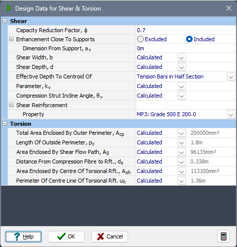
This form enables the parameters used in the Ultimate Limit State shear width and torsion calculations to be defined. Details of each parameter and the defaults supplied are contained in the help messages for the individual fields.
Form Graphic
Field Help
Shear
Capacity Reduction Factor, ϕ
The Capacity Reduction Factor is specified in this field.
The default value is 0.70 according to Table 2.3.2 of AS 5100.5-2017. The program allows any value from 0 to 1.0 to be entered.
Enhancement Close To Supports
This field enables the shear strength enhancement close to supports which is allowed by Clause 8.2.7 of AS 5100.5 to be excluded from the calculations. In this case the value of the coefficient β3 will always be taken as 1.0.
Dimension From Support, av
AS 5100.5 allows an enhancement of shear strength for sections near supports, and various articles refer to 'the face of the support'.
The value entered in this field defines the distance from the support of the beam to the point described by the code as 'the face of a support'.
For a rigid bearing, it is appropriate to take the front edge as the face of the support. For a flexible bearing, it is appropriate to take the centerline.
Shear Width, b
Shear Depth, d
In the calculations for shear resistance in the section,
- the default value for the width of the section resisting shear, b, is taken as the width of the section at the level of the centroid.
- the default value for the effective depth of the section is estimated from the overall depth of the section at its centroid as follows:
- the distance defined by the field labelled 'Effective depth to centroid of'.
- for post-tensioned beams, or sections with prestressed reinforcement only: depth of the section less the distance to the centroid of all the prestress tendons at the section.
For most sections these should provide suitable values. For some shapes however, this may result in an unsuitable value (e.g. for the effective depth d for circular columns). For this reason provision is given here to override the default value by choosing User Defined and entering a value in the adjacent field.
Effective Depth To Centroid Of
For the effective shear depth definition, choose between:
- Outermost Bar
The distance from the extreme compression fibre to the centre of the outermost tension bar or prestressed reinforcement. - Tension Bars in Half Section
The distance from the extreme compression fibre to the centroid of the longitudinal tension reinforcement in the half-depth of the section containing the flexural tension zone (default).
Parameter, kv
kv is calculated according to Clause 8.2.4.2 of AS 5100.5-2017. To override this calculated value choose User Defined and enter a value in the adjacent field.
Compression Strut Incline Angle, θv
This field is used to override the angle of inclination of the concrete compression strut with the longitudinal axis of the member. If set to User Defined, the user specified value is used, otherwise the angle is calculated in accordance with Clause 8.2.4.2 of AS 5100.5-2017. Default user value is 20° (for prestressed concrete members).
Shear Reinforcement: Property
An appropriate material property set will be selected from the property sets that have already been defined, and assigned to the component by default. An alternative property set may be entered if a suitable one has been defined.
Torsion (AS 5100.5-2017 only)
Total Area Enclosed By Outer Perimeter, Acp
This parameter represents the total area enclosed by outside perimeter of concrete section according to Clause 8.2.1.2 of AS 5100.5-2017.
To override the calculated value, set to User Defined and enter a value in the adjacent field.
Length of Outside Perimeter, pc
This parameter represents the length of the outside perimeter of the concrete cross-section according to Clause 8.2.1.2 of AS 5100.5-2017.
To override the calculated value, set to User Defined and enter a value in the adjacent field.
Area Enclosed By Shear Flow Path, Ao
This parameter represents the area enclosed by the shear flow path, including any area of holes therein according to Clause 8.2.1.2 of AS 5100.5-2017.
The default value for cellular sections is defined by the area of a polygon drawn in between the outer perimeter and the minimum convex perimeter around the voids. For solid sections the default value is 0.85*Aoh, as calculated in Clause 8.2.5.6 of AS 5100.5-2017.
To override the calculated value, set to User Defined and enter a value in the adjacent field.
Distance from Compression Fibre To Rft., ds
This parameter represents the distance from the extreme compression fibre to the centroid of non-prestressed tensile reinforcement according to Clause 8.2.1.2 of AS 5100.5-2017.
The default value is zero if no bars are defined.
To override the calculated value, set to User Defined and enter a value in the adjacent field.
Area Enclosed By Centre Of Torsional Rft., Aoh
This parameter represents the area enclosed by the centre-line of exterior closed transverse torsional reinforcement, including area of holes (if any) according to Clause 8.2.4.5 of AS 5100.5-2017.
The default value is based on torsional reinforcement with an offset from the concrete surface calculated as: offset = nominal concrete cover + 0.5 x diameter of the torsional reinforcement Nominal cover and diameter of the torsional reinforcement can be set via the Serviceabilty parameters. For cellular sections, in case Aoh is calculated less than Ao, the default value becomes Aoh = Ao / 0.85;
To override the calculated value, set to User Defined and enter a value in the adjacent field.
Perimeter Of Centre Line Of Torsional Rft., uh
This parameter represents the perimeter of the centre-line of the closed transverse torsional reinforcement according to Clause 8.2.1.2 of AS 5100.5-2017.
The default value is based on torsional reinforcement with an offset from the concrete surface calculated as: offset = nominal concrete cover + 0.5 x diameter of the torsional reinforcement. Nominal cover and diameter of the torsional reinforcement can be set via the Serviceabilty parameters. For cellular sections, in case Aoh is calculated less than Ao, the default value for the perimeter becomes uh = uo / sqrt(0.85), where uo is the perimeter of the shear flow path.
To override the calculated value, set to User Defined and enter a value in the adjacent field.