
Virtual Members
Description
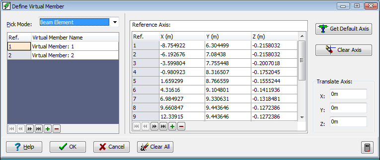
This form is used to define Virtual Members. A virtual member is a combination of beam elements / finite elements for which a single set of results effects is required at any given section.
Two stages are required. The first defines the beam/finite elements that comprise the virtual member. The second stage defines the virtual member axis, which is a series of points at which the composite effects are calculated. Effectively a plane is constructed which is perpendicular to the virtual axis, and all those virtual member components that intersect this plane have their effects resolved to a single composite effect. The virtual member axis also defines the virtual member local axes system, according to the same convention as beam elements.
Inclusion of highly skewed elements in virtual member definitions may degrade the accuracy of results.
Outline Procedure
This form is accessed through Calculate | Define Virtual Member in the Main Menu.
Define Virtual Member Components:
In the field labelled 'Pick mode' select either beam or finite element type. This is to assist when using boxes to select the members.
Selection is now carried out with the mouse on the display area. Either:
- Select a single member of the type defined in the 'Pick mode' field. The member will turn red, indicating that the current member has been included, or
- Box around a group of members on the display. All of the boxed members that are of the appropriate type will be included in the virtual member definition, and will be shown selected. (This may include hidden elements).
The virtual member title may be modified in the column headed 'Title'. (e.g. 'Mid-span Virtual Memb').
If the structure properties of a 'Pre-tensioned Prestressed Design Beam' are to be applied then an alternative method of defining these virtual member components is to assign them to a span in a bridge deck. Please refer to the Offset Beam or Tub Girder topic for further information.
For details of the table features, and navigation, see the help topic Table Features & Navigation
To define additional virtual members click on the + button at the bottom of the left table, and repeat the above procedures.
Define Virtual Member Axis
If construction stages are defined, there will be one reference axis table per construction stage, enabling the reference axis to be varied between construction stages according to the member components present at the construction stage.
If the virtual member is automatically created via the model generation forms (refer to the Offset Beam or Tub Girder topic), the reference axis is generated based on the section data contained in the associated design beam. For an automatically generated virtual member which also includes construction stages, this will take into account the presence of the finite element slab elements and their modular ratio at each construction stage.
For manually created virtual members the simplest way to define the reference axis is to click on the Get Default Axis button. A series of points will be generated and will appear in the table on the right of the form. The default axis is calculated as follows:
- Z for all points is taken as the maximum Z coordinate of any component of the virtual member.
- For virtual members that comprise finite elements only, the application looks at the footprint of the virtual member elements on the X-Y plane, constructs a box around this and takes an axis that bisects the box in line with its longer edge. A point along the axis will be generated at each location where the edge of a component element intersects the axis.
- For virtual members that comprise beam members only, or beam members and finite elements, the application finds a beam or element edge in the Z plane of the default axis, and constructs the axis from all beams or element edges that are in the same plane and are co-linear.
An alternative method is to select 'Node' form the field labelled 'Pick mode', and click on those nodes in the structure that may be used to define an appropriate axis.
Whatever method is used, a translation in the global X, Y, Z directions may be applied to the axis at any time by entering values in the 'Translate Axis' fields.
Special Mouse Actions
A beam or finite element can be deleted from the virtual member definition by setting the select mode to 'Remove'. The select mode can be set via the Select item on the graphics window toolbar.
Form Graphic
Field Help
Pick Mode
The pick mode is set to 'Node' for definition of the virtual member axis. With other options selected, the members and elements comprising the virtual member will be selected.
Virtual Member Name
A name that is used for identifying the virtual member is generated by the application. The name will appear when selecting members for results output.
The default name may be changed by entering an alternative name in this field.
Reference Axis
The virtual member axis is defined from a string of points in 3D space, whose coordinates are contained in this table. When the pick mode is set to 'Node', nodes in the model may be selected. The nodes will be sorted into order of distance from the first node selected.
The virtual member local axes directions follow the same conventions as for beam elements.
Translate Axis
The points on the virtual member axis may be translated by entering a value in these fields. On exiting any field the table and graphics are updated, and the value in that field is reset to zero.
The points may also be edited directly in the table.
Get Default Axis
Click this button to generate a default virtual member axis. The manner in which this is calculated is described above (under 'Define Virtual Member Axis').
Clear Axis
Click this button to clear all the virtual member axis data.