
Early Thermal Crack Control
Description
A comprehensive series of data checks are carried out before the calculations are performed and the results displayed.
The reinforcement required for early thermal cracking is displayed in the field labelled 'Reinforcement area required'. The actual area of reinforcement currently present is also displayed. Note however that reinforcement for resisting cracking must be evenly distributed around the surface of the section. The program makes no allowance for this in calculating the total area present.
The graphics window shows the cross section with the concrete 'core' area hatched (unless an alternative area has been specified in the data). Detailed results for all the construction stages present at the section are available in the printout, which can be viewed on the screen by pressing the F5 key or clicking on the Results button.
Form Graphic
Field Help
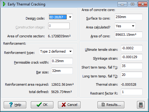
Design code
Select the design code which will form the basis of the early thermal cracking calculations. The available options are:
- BS 5400 Part 4 1990. 'Code of practice for the design of concrete bridges.'
- BD 28/87. Department of Transport Design Manual for Roads and Bridges. 'Early thermal cracking of concrete.' This option includes the amendments given in amendment 1 to BD 28/87, which are dated 1989.
Construction stage
The calculations may be carried out for each stage of construction separately. The required construction stage is selected from this field.
Surface to core
Area calculated
Area of core
The calculation in BS 5400 requires the gross area of the concrete section, and the area of the 'core' i.e. that portion of the section more than 250mm away from all concrete surfaces.
The calculation in BD 28/87 requires the gross area of the concrete section, and the area of effective concrete, which is the same as the gross area less the core.
The gross area and area of the core are calculated automatically by the program. The core area is shown hatched in the graphics window.
The program makes allowance in its calculation of these areas for sides of the elements which have been designated in the data as cut lines in continuous structures such as wide slabs.
The values of all of these areas may be over-ridden. Select 'No' in the field labelled 'Area calculated?' to allow access to the following field for entry of a specific value for the concrete core area. In this case, clearly, no core will be shown in the graphics window.
Reinforcement type
The type of reinforcement may be specified as:
- plain round bars
- Type 1 deformed bars (twisted)
- Type 2 deformed bars (ribbed)
The classification of bars as Type 1 or Type 2 is in accordance with BS 5400 Part 4, clause 5.8.6.1.
Permissible crack width
The permissible crack width should be taken from the values in Table 1 of BS 5400 Part 4 for the appropriate environment.
Bar size
Enter the value of the bar diameter to be used in the calculations. The default size is the largest bar diameter found in the section.
Ultimate tensile strain
The default value for the ultimate tensile strain capacity of the concrete may be taken as 200 μstrain, in accordance with BD 28/87. If an alternative value is required, it may be entered in this field.
Shrinkage strain
The shrinkage strain should be taken as the free shrinkage strain, modified by the effects of creep. For an estimate of the free shrinkage strain and the creep reduction factor refer to BS 5400 Part 4 Appendix C.
For normal UK conditions, the shrinkage strain is usually not more than 0.5 times the ultimate tensile strain.
Short term temp. fall T1
Enter the short-term fall in temperature from hydration peak to ambient conditions (T1).
Suitable values in degrees Celsius for OPC members up to 500mm thick are as follows:
| < | FORMWORK | > | ||
|---|---|---|---|---|
| Cement content | < STEEL | > | < 18mm PLYWOOD | > |
| (kg/m3) | Winter | Summer | Winter | Summer |
| 300 | 12 | 18 | 20 | 28 |
| 350 | 15 | 23 | 27 | 35 |
| 400 | 17 | 27 | 32 | 43 |
For sections thicker than 500mm, increase the above values by 10 degrees.
If SRPC is specified, reduce the values from the table by 20%
If RHPC is used or an accelerating admixture, for concreting in very cold weather, use the value as for OPC in summer conditions.
The value in the field labelled 'Thermal strain' is calculated from T1 and T2, using the formula from paragraph 5.7 of BD 28/87:
strain = 0.8 x alpha x (T1 + T2)
For further details refer to BD 28/87.
Long term temp. fall T2
Enter the long-term fall in temperature from ambient to the seasonal minimum (T2).
Suitable values are 20 degrees for summer concreting, and 10 degrees for winter concreting.
T2 may be ignored (enter as 0.0 degrees) if:
- full movement joints are provided at no more than 15m spacings.
- the restraint is being provided by a section subject to the same climatic exposure as that being restrained.
The value in the field labelled 'Thermal strain' is calculated from T1 and T2, using the formula from paragraph 5.7 of BD 28/87:
strain = 0.8 x alpha x (T1 + T2)
For further details refer to BD 28/87.
Restraint factor R
The restraint factor R represents the amount of restraint to lateral and shrinkage movement which is actually provided, normally by previously cast elements of the structure. The value of the factor depends on the nature of the structural elements concerned and typical values of R for different examples of restraint are given by BD 28/87 as follows:
| RESTRAINT CONDITION | RESTRAINT FACTOR (R) |
|---|---|
| External: | |
| Base cast onto blinding | 0.2 |
| Edge restraint in box type deck cast in stages | 0.5 |
| Wall cast onto base | 0.6 |
| Edge element cast onto slab | 0.8 |
| Infill bays | 1.0 |
| Internal: | 0.5 |