Create base/edge/contour flange
Create base, edge, and contour flanges using the Flange![]() feature in the Design workspace in Fusion.
feature in the Design workspace in Fusion.
Create a base flange
On the Sheet Metal tab, select Create > Flange
 .
.The Flange dialog appears.
In the dialog, select the Flange (Base/Edge/Contour)
 type.
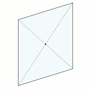
type.On the canvas, select one or more closed sketch profiles.
Note: If you select multiple closed profiles that are not connected, each profile creates a separate body.Select the Orientation of the sheet metal material:
- Side 1
 : Extrudes a flat sheet metal material to one side of the sketch profile.
 - Side 2
 : Extrudes a flat sheet metal material to the opposite side of the sketch profile.
 - Center
 : Extrudes a flat sheet metal material evenly on both sides of the sketch profile.
- Side 1
Select an Operation:
- New Body
 : Creates a separate sheet metal body within the active component.
 - New Component
 : Creates a new sheet metal body in a separate component.
- New Body
Click OK.
The base flange appears as a sheet metal body on the canvas and in the Browser, nested in the Bodies folder of the active component. A Base Flange
 feature appears in the Timeline.
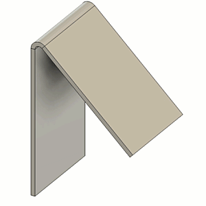
Create an edge flange
Repeat steps 1-2 from the Create a base flange task.
On the canvas, select one or more edges on a sheet metal body.
Specify how the flange extends:
- Distance (default): Specify the Height to extrude the flange from the height datum:
- On the canvas, drag the distance handle.
- Or specify an exact value.
- To Object: Extend the flange until it meets a selected face, plane, or body. This option is only available when you select a single edge, as multiple edges can extend in different directions and Fusion cannot determine where to extend. The target object must be planar (cannot be round or curved) and must lie on a plane that is parallel to the edge being extended.
- In the Flange dialog, set Extent Type to To Object.
- On the canvas, select the face, plane, or body to extend to.
- (Optional) Specify an Offset value to offset the flange from the selected target object.
- Distance (default): Specify the Height to extrude the flange from the height datum:
Specify the Angle of the flange relative to the selected sheet metal edges:
- On the canvas, drag the rotation handle.
- Or specify an exact value.
In the selection box, select a Flange Width Type for each selected sheet metal edge, and adjust its associated settings below the selection box:
- Full Edge
 : Creates a flange along the entire length of the selected edge.
 - Symmetric
 : Creates a flange of a specified distance centered on the mid-point of the selected edge.
- Distance: Specifies the overall distance of the flange, centered on the mid-point of the selected edge.
- Two Sides
 : Creates a flange centered on the mid-point of the selected edge with two adjustable width extents on both sides.
- Distance 1: Specifies the distance to extend one side of the flange from the mid-point of selected edge.
- Distance 2: Specifies the distance to extend other side of the flange from the mid-point of selected edge.
- Two Offsets
 : Creates a flange positioned between two selected reference faces, with adjustable offsets from each face.
- Reference 1: Select a face, point, or plane to define the reference for one side’s offset.
- Offset 1: Specifies the distance from Reference 1 to extend the flange on one side.
- Reference 2: Select a face, point, or plane to define the reference for the other side’s offset.
- Offset 2: Specifies the distance from Reference 2 to extend the flange on other side.
- Full Edge
(Optional) If you selected Distance as the extent type, select the Height Datum to measure the flange height:
- Inner Faces
 : Sets the height reference to the intersection on the inner faces of the base flange and the new flange.
 - Outer Faces
 : Sets the height reference to the intersection on the outer faces of the base flange and the new flange.
 - Tangent To Bend
 : Sets the height reference tangent to the bend between the base flange and new flange, parallel to the new flange.
- Inner Faces
Select the Bend Position:
- Inside
 : Places the bend inward, so it starts inside the outer edges of the base and new flange.
 - Outside
 : Places the bend so it extends beyond the inner edges of the base and new flange.
 - Adjacent
 : Places the bend so that it starts at the selected edge on the flange.
 - Tangent
 : Places the bend so that it is tangent to the selected edge on the flange.
- Inside
(Optional) If you selected Distance as the extent type, you can Flip
 the flange 180 degrees over the base flange.
(Optional) Select Miter Corners to miter the corners where sheet metal corners would otherwise overlap.
(Optional) Select Override Rules to change one or more default values from the Sheet Metal Rule for this operation only. This does not change the values in the Sheet Metal Rule itself.
Click OK.
The flange is added to the sheet metal body on the canvas. An Edge Flange
feature appears in the Timeline.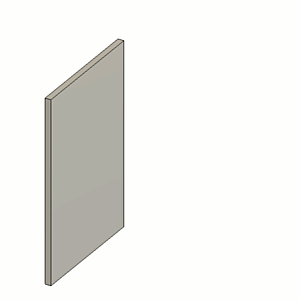
Create a contour flange
Repeat steps 1-2 from the Create a base flange task.
On the canvas, select one or more open sketch profiles.
Note: If selecting multiple open sketch profiles, they must be on the same plane.Specify the Distance to extrude the flange from the profile:
- On the canvas, drag the distance handle.
- Or specify an exact value.
Select the Orientation of the sheet metal material:
- Side 1 : Extrudes sheet metal material to one side of the sketch profile.
- Side 2 : Extrudes sheet metal material to the opposite side of the sketch profile.
- Center : Extrudes sheet metal material evenly on both sides of the sketch profile.
- Side 1
Select the Direction to extrude the contour flange from the profile:
- One Side
 : Extrudes flange on one side of the profile plane.
 - Two Sides
 : Extrudes flange unevenly on each side of the profile plane.
 - Symmetric
 : Extrudes flange evenly on both sides of the profile plane.
Note: Each contour flange creates a new body.- One Side
Select an Operation:
- New Body : Creates a separate sheet metal body within the active component.
- New Component : Creates a new sheet metal body in a separate component.
- New Body
(Optional) Select Bend Override to update the Bend Radius value from the default specified in the Sheet Metal Rule for this operation only. This does not change the bend radius value in the Sheet Metal Rule itself.
Click OK.
The contour flange appears as a sheet metal body on the canvas and in the Browser, nested in the Bodies folder of the active component. A Contour Flange
 feature appears in the Timeline.
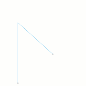
Create a contour flange and join it to a sheet metal edge
Sketch or project an open sketch profile on a plane that is normal to the sheet metal edge you want to bend.
Repeat steps 1-2 from the Create a base flange task.
On the canvas, select the sheet metal edges and the open sketch profile.
Note: You can select the open sketch profile and the sheet metal edge in any order.In the selection box, select a Flange Width Type for the selected sheet metal edge, and adjust its associated settings below the selection box. For all available settings, see step 5 in the Create an edge flange section above.
Select the Orientation of the sheet metal material. For all options, see step 4 in the Create a contour flange section above.
(Optional) Select Override Rules to change one or more default values from the Sheet Metal Rule for this operation only. This does not change the values in the Sheet Metal Rule itself.
Click OK.
The contour flange is created and joined to the sheet metal body on the canvas. A Contour Flange
feature appears in the Timeline.
Tips
Hold
Ctrl(Windows) orCommand(MacOS) to modify the selection set once the sheet metal flange preview displays on the body on the canvas.Select Override Rules to override one or more values from the Sheet Metal Rule assigned to the component.
Select Miter Corners to miter the corners where sheet metal corners would otherwise overlap.