
System Modeler
This feature is part of an extension. Extensions are a flexible way to access additional capabilities in Fusion. Learn more.
System Modeler brings visual scripting to engineering workflows in Fusion. Instead of writing code, you connect nodes on the canvas. Each node performs a specific operation, and data flows through the wires between them. Use it to automate repetitive tasks (such as creating geometry, configuring manufacturing setups, and generating toolpaths) or build reusable engineering workflows.
How System Modeler works
A workflow in System Modeler is called a graph. A graph is built from two building blocks:
Nodes are the individual operations. Each node receives input values, processes them, and produces output values. Nodes cover a wide range: from simple math and list operations to complex geometry creation and CAM configuration.
Wires connect one node's output to another node's input. Data travels along the wires from left to right as the graph runs. The path the data takes is visible on the canvas before you ever run the graph.
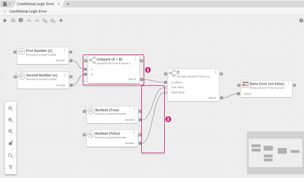
Base - Conditional Logic Error
Nodes come from packages. A package is a versioned collection of nodes organized into categories, together with sample graphs you can open and learn from. Fusion provides about 500 ready-to-use nodes in the following packages:
- Base: Universal nodes for math, logic, lists, text, and control flow, independent of Fusion
- System: Foundational Fusion operations covering documents, geometry, 3D math, HTTP, and logging
- Design: Design modeling covering sketches, BRep geometry, components, appearances, and features
- Manufacture: Manufacturing operations covering setups, tool libraries, CAM operations, and NC programs
You can also create user packages to store and share your own graphs. See Packages.
Access System Modeler
System Modeler is available in the Automation tab in the Design and Manufacture workspaces. It runs as an add-in, so you need to enable it before it is visible in the ribbon. For steps, see Get started with System Modeler. After you enable it, click the Automation tab in the ribbon, then click System Modeler.

System Modeler workflow
- Browse the Library. The Library panel lists all loaded packages and their category folders. Expand a package to see its categories, then click a category to view its nodes.
- Build a graph. Drag nodes from the Library onto the canvas and connect their ports with wires. Data flows left to right, from source nodes through transformations to outputs.
- Run the graph. Click Save and run the graph
 on the toolbar, or press Ctrl+R (Windows) / Command+R (macOS). The graph processes the active Fusion document. Graphs can also import, open, or create new documents.
- Review results. After the run, each node shows a diagnostic badge. Open the Diagnostics tab in the Details panel for the full list of outcomes and run times.
- Save and share. Click Save
 or press Ctrl+S (Windows) / Command+S (macOS) to save your graph to a user package. Export the package to share it with others or back it up.
What you can do
As your graphs grow, you can:
- Apply loops, conditional logic, and subgraphs to handle real-world complexity
- Span multiple domains in a single graph, including design and manufacturing
- Start with a single automated step and grow the graph into a full cross-domain workflow
The same graph you author is the artifact your team runs, reviews, and changes.