
Activity 4: Constrain and load the steel slab
In this activity you apply appropriate constraints to the large steel slab to model the true physical process of rolling it. The steel slab needs two structural constraints (zero displacement boundary conditions) so it can move only in the +X direction under the roller, and it can be flattened in the -Y direction.
The steel slab is moved by the pusher block and the roller. At the start of the analysis the roller and the pusher block are already in motion, so to replicate the true process you need to ensure the steel slab is also in motion at the start. The steel slab must have an initial velocity in the X-direction that matches the prescribed velocity boundary condition on the pusher block.
In this activity, you apply:
- A fixed structural constraint to the front and back faces of steel slab in the +Z and -Z directions, so that it can still move under the roller, but it won't move sideways off the rollers
- A fixed structural constraint to the bottom face of the steel slab, where it slides along the rollers (not modelled), in the +Y direction so that it can be flattened but won't squeeze through the rollers.
- An initial linear velocity so the steel slab is already moving at the appropriate speed at the start of the event and isn't shocked by an instantaneous acceleration.
Prerequisites
- Activity 3 is complete.
Steps
Apply a Fixed Constraint to the front and back faces of the metal slab, in the Z-direction.
Click
 (Simulation workspace > Setup tab > Constraints panel > Structural Constraints), to open the Structural Constraints dialog.
Confirm the constraint Type is set to Fixed.
Click the front and back faces of the steel slab to select them as Targets.
Note: You will need to rotate the model to access both the front and the back faces.Click on Ux and Uy to deselect them, so that only Uz is selected.
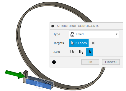
Click OK to set the constraints and close the dialog.
Constrain the bottom face of the steel slab, where it slides along the rollers, in the Y-direction.
Click
(Simulation workspace > Setup tab > Constraints panel > Structural Constraints), to open the Structural Constraints dialog.Confirm the constraint Type is set to Fixed.
Click the bottom face of the steel slab to select it as the Target.
Click on Ux and Uz to deselect them, so that only Uy is selected.
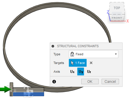
Click OK to set the constraints and close the dialog.
Apply an Initial Linear Velocity to the steel slab of 41000 mm/s in the X-direction.
Click
 (Simulation workspace > Setup tab > Loads panel > Initial Linear Velocity), to open the Initial Linear Velocity dialog.
Select the steel slab in the canvas to select it as the Body.
Click
 Change Units and switch the units to mm/s.
Set the Velocity in the X-direction to 41000 mm/s.
Note: An orange arrow appears, pointing in the same direction as the green arrow, to indicate the direction of the initial linear velocity.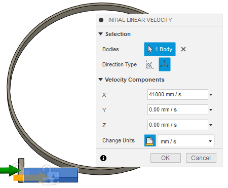
Click OK to apply the load and close the dialog.
Activity 4 summary
In this activity, you
- applied a fixed structural constraint to the front and back faces of steel slab in the +Z and -Z directions
- applied a fixed structural constraint to the bottom face of the steel slab in the +Y direction
- applied an initial linear velocity to the steel slab of 41000 mm/s in the X direction.