
Bearing loads in the Simulation workspace
Bearing loads are used to simulate the effects of cylindrical faces or bodies pushing against one another. A common case is a pin (or bolt) pushing against the wall of a hole. With a bearing load, you can simulate this interaction without the need to include both interacting bodies.
| Study Types that offer this load option | |
|---|---|
 Thermal stress study Thermal stress study |
 Static stress study Static stress study |
 Modal frequencies study Modal frequencies study |
 Structural buckling study Structural buckling study |
 Shape optimization study Shape optimization study |
 Nonlinear static stress study Nonlinear static stress study |
The Bearing load is applied to the selected face in a parabolic distribution. This distribution is typical of the loading pattern that occurs naturally between shafts and bearings or between bearings and housings. Unlike a Force load, a Bearing load is always directed into the face and never acts in tension (it can only push, not pull). For example, a bearing load applied to a full 360° cylindrical face is distributed around half of the face (180°), and the other half of the face is not loaded.
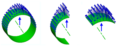
The following image demonstrates the force distribution pattern of an upward Bearing Load acting against the face of a hole. Three different situations are shown:
Full cylinder
Half-cylinder with the force vector passing through the edges of the face
60° segment with the force vector passing through the center of the face
 .
.
You can define the force direction of a bearing load in the following ways:
 Angle (delta) : The direction is always radial, based on the selected cylindrical surface.
 Vectors (x,y,z) : using the global force components (Fx, Fy, and Fz).
 Reference : The direction is always radial, based on the selected cylindrical surface. Choose a reference entity to finalize the vector orientation, as follows:
- Face (flat faces only): The vector direction is normal to the selected face.
- Edge (straight edges only): The vector direction corresponds to the selected edge orientation.