
Activity 1: Setup a new electronics cooling study
In this activity you create an electronics cooling study, and apply internal heat loads and temperature thresholds to the two regulators, to see how hot the board components get, and whether the two regulators exceed their threshold temperatures.
To run the analysis you need tokens in your account, or an active subscription to the Fusion Simulation Extension. If you don't already have a subscription to the Fusion Simulation Extension, you can access the 7-day free trial to gain access to all the Simulation studies for 7 days. To set up the study, you
Save the model to a personal folder
Create an electronics cooling study
Check the materials
Change gravity so it is applied in the -Z direction
Apply heat loads to the regulators
Assign temperature thresholds to the regulators
Solve the study.
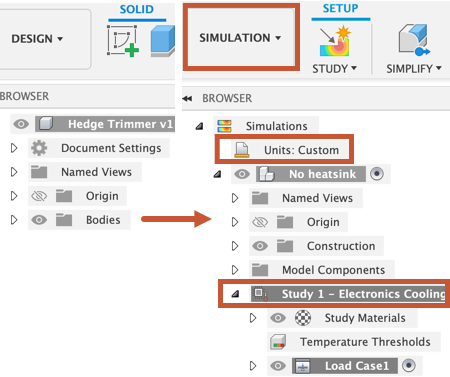
Browser when model is first imported (left). Browser after creating a new Electronics cooling study (right).
Prerequisites
Fusion is started.
Tokens, or an active subscription to the Fusion Simulation Extension.
Data file location: Samples > Basic Training > 11-Simulation > PowerSupplyEnclosure.
Note: If you have neither tokens nor an active subscription to the Fusion Simulation Extension, you can still follow the tutorial by using sample files. In the Data Panel, you can find predefined sample files that are fully setup ready to run, and ready with results, so you can practice interpreting them. You can open them and start learning at any point you want: Simulation Samples.
Steps
Open the starting shape model, PowerSupplyEnclosure, in the Z up direction from the Basic Training folder in the Data Panel.
If the Data Panel is not currently shown, click
 Show Data Panel at the top of the screen.
The top level (home view) of the Data Panel is divided into two subsections: ALL PROJECTS and SAMPLES. Scroll down until you reach SAMPLES.
Double-click the Basic Training folder to open it.
Double-click the 11 - Simulation folder to open it.
Double-click the PowerSupplyEnclosure model to open it in the canvas.
Note: The sample model is read-only, so you must save a copy of it to a personal project.
Identify a personal project in which to save the starting shape model.
- Select
 File > Save as.
 - Enter a name, such as PowerSupplyEnclosure, in the name field.
- Expand the arrow button next to the Location field.
- Locate and click on an existing project, or click New Project to start a new project.
- Select
Identify or create a folder in which to save the starting shape models.
- Double-click on a folder in the project to select it, or create a new folder.
- To create a new folder, select New Folder.
- Type a name, such as Power Supply tutorial for the folder.
- Press Enter.
- Double-click the folder to make it the current file saving location.
- Select Save.
Create a new Electronics Cooling study, and name it 50 W no fan.
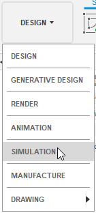
Click on the Change Workspace drop-down menu at the top left end of the toolbar and select Simulation
In the New Study dialog box, select
 Electronics Cooling.
Click Create Study to create the study and close the dialog.
In the Simulation workspace, in the Browser, click Study 1 - Electronics Cooling to activate edit mode and rename the study 50 W no fan
Check that the materials for the board and the various components are appropriate.
In the Simulation workspace, on the Setup tab toolbar, select
 (Materials > Study Materials) to open the Study Materials dialog.Note: By default, each body has a material assigned to it that is the same as the material selected for the Design model.
Scroll through the component list and notice that some components use materials from the electronics library, such as FR4 and Discrete Component. This model was created in the Fusion Electronics workspace and attributes assigned in that workspace are imported automatically into the Simulation workspace.
When you have finished reviewing the materials, click Cancel to close the Study Materials dialog.
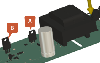
Apply an Internal Heat load of 1.0 W to the voltage regulator (A) closest to the signal transformer, and 50.0 W to the 2nd regulator (B) further from the transformer.
- On the Setup tab toolbar, select
 (Loads > Thermal Loads) to open the Thermal Loads dialog.
 - In the Thermal Loads dialog, set the Type to Internal Heat.
- In the canvas, select regulator A, shown in the image, then confirm that 1 Body has been selected in the Thermal Loads dialog.
- In the Thermal Loads dialog, set the Heat Load to 1 W.
- Select OK to accept the command and close the Thermal Loads dialog.
- Repeat the steps, but in the canvas select regulator B and in the Thermal Loads dialog set the Heat Load to 50 W.
- On the Setup tab toolbar, select
Assign a Maximum Temperature threshold of 130 C to each of the two regulators. This is the maximum temperature that the regulators can reach before they risk failure.
Note: The Temperature Thresholds result and the Threshold Guided Result are only generated when you assign a temperature thresholds to board components.On the Setup toolbar, select
 (Solve > Pre-check), to open the Pre-check dialog.
Notice that there is a yellow warning icon which indicates that although the study can be solved, some inputs may not be ideal. In this case, we haven't assigned temperature thresholds to any components. You can run the study without temperature thresholds, but without temperature thresholds the Threshold Guided Result and the Temperature Thresholds result are not generated.
On the Setup toolbar, select
 (Thresholds > Temperature Thresholds) to open the Temperature Thresholds dialog.
In the canvas select the two regulators and confirm they are both highlighted in blue.
In the Temperature Thresholds dialog enter 130 and press return on your keyboard.
Note: Scroll up and down the Temperature Threshold dialog to confirm that both regulators have a Maximum Temperature set at 130 C.In the Temperature Thresholds dialog, click OK to apply the changes and close the dialog.
Change the direction that gravity is applied, to the -Z direction.
On the Setup toolbar, click
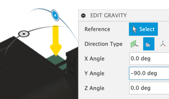
 (Environment > Edit Gravity) to open the Edit Gravity dialog.
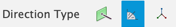
In the Edit Gravity dialog, change the Direction Type to Angle (delta).
In the canvas, use the manipulators to rotate the gravity direction until the Y Angle reads -90.0 deg.
Click OK to apply the changes and close the dialog.
Check that the study is setup properly, then run the analysis.
On the Setup toolbar, check
 (Solve panel > Pre-check), and confirm it is green with a white check mark.
On the Setup toolbar, click
 (Solve panel > Solve), to open the Solve dialog.
In the Solve dialog, click Solve 1 Study to run the analysis and close the dialog.
Note: Meshing and solving the analysis can take several minutes.When the analysis is complete, click Close to close the Job Status dialog.
Activity 1 summary
In this activity you created an Electronics Cooling study to see how hot the board components get, and whether the two regulators exceed their maximum temperature thresholds. To set up the Electronics Cooling study you
- Saved the model to a personal folder
- Created an Electroncis Cooling study
- Selected the desired units system
- Checked the materials selection
- Applied heat loads to the regulators
- Assigned temperature thresholds to the regulators
- Changed the applied gravity to the -Z direction.
- Solved the study.