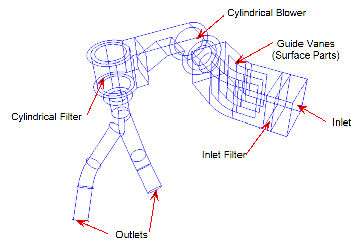
In this HVAC duct system, air flows through several filters and a centrifugal blower and then exits through two distribution tubes.
The geometry consists of air volumes and several internal components. The typical CAD production model typically also includes the duct wall parts. We have omitted them from this tutorial, however, because we are not concerned with heat transfer. If the objective was to understand how the ducts affect the temperature distribution, we would have included the duct wall parts in the geometry.

In this tutorial, we will explore how to use a centrifugal blower material and a cylindrical distributed resistance. Both of these material objects are sensitive to the settings applied on the Materials dialog, so please pay particular attention when defining these.
We will use Surface Parts to simulate the presence of thin-walled sheet metal guide vanes in the duct. In the Pro/Engineer, SolidWorks, and Parasolid versions of the geometry, the guide vanes were modeled with surfaces that were not a part of any 3D part in the CAD model. In Autodesk® Inventor, Solid Edge, and Acis, three dimensional volumes were constructed such that their sides are the guide vanes. These volumes are treated as fluid regions, and the sides are assigned a solid material. This is a different way to use Surface Parts in a Autodesk Simulation CFD analysis model.
Key Topics
- Distributed resistances not aligned to a Cartesian axis
- Centrifugal blower material object
- Cylindrical distributed resistance (for a filter)
- Surface Parts to simulate sheet metal obstructions
Goal
The objective of this analysis is to compare the flow rates from the two outlets.