This table defines the various types and allowances associated with the connectors, which are used to join two items together. There is no limit to the number of connectors that can be defined in the software. Connectors are separated into three separate connector types.
Connectors are an integral part of every Product and define the method for joining one Item to the next. Each Open end of a Pipe, Fitting or Equipment usually have connectors assigned. 3rd party Objects can have Connectors assigned through the Object Wrapper utility. Connectors are sub-divided into Rectangular, Round and Oval Libraries. Each Library may be further broken into Groups of like Connectors. Pipe Work Connections are defined from the Round Library. Connectors are auto attached to Products through Specifications.
Please use the Navigation & Toolbars for information on how to access the Global database using your application.
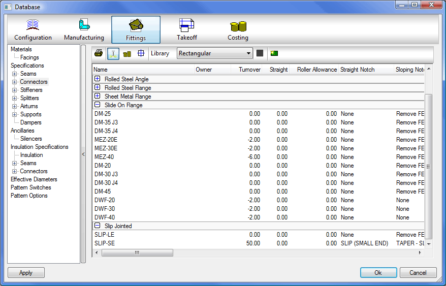
To amend any of these details, double-click on the relevant connector name (or right-click and choose Edit), to create a new connector click on the  Icon ensuring you are within the relevant library. In either case, you will be presented with a dialogue box similar to the following one.
Library
Choose from the list which table is to be reviewed or edited.
Rectangular Connector Table
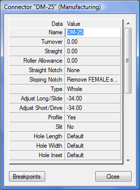
The following can be defined for each connector.
Name
Enter the name which describes the connector. Try to keep the name as short as possible since some dialogue boxes only display a limited number of characters.
Turnover
This value defines the extra metal allowance required to form the connector. This value will always be added to the duct.
Straight
The Straight option on the Connector would only affect the area of an item if you have no extensions set. The straight option is intended to leave that amount of straight on the ends of the duct to accommodate for connectors/flanges. Typical examples where this would be altering the area would be on Tapers or Radius bends that have no extension on them. In a radius bend for example that has no extensions, the straight option would cut back into the duct and alter the radius to accommodate for this. Only in this circumstance would it alter the area on patterns and where the straight option value is larger than the extension of the duct. Straight patterns would be unaffected.
Roller Allowance
This is the values used when the part is Oversized and has to be sliced, this will cut back the allowance on the Oversized Seam so that the seam rollers wont seam over the Connector Allowance. This is used in conjunction with the settings in the Oversized Seam.
Straight Notch
This is the notch used to remove connector / seam intersections.
Sloping Notch
This is the notch used in situations such as transitions and drop cheeks. Its primary usage is to remove taper extensions.
Type
The pull down menu lists the different types of connector setting, details of which are listed below.
- Whole One connector per duct end.
- Shared One connector for every two duct ends assigned.
- S & D Auto The "C" drive cleat will automatically be assigned to the longest of the two sides, either the width or depth. This type is shared.
- D & S Auto The "S" cleat will automatically be assigned to the longest of the two sides, either width or depth. This type is shared.
- S & D Manual The "C" drive cleat will always be assigned to the width. This type is shared.
- D & S Manual The "S" cleat will always be assigned to the width. This type is shared.
Adjust Long / Slide / Adjust Short / Drive
These values are added or subtracted from the length of the connectors flange material, when lengths are shown on reports.
Profile
This determines whether the connector is an external (Yes) or self flange (No).
Slit
The options here are as follows:
- No: Nothing will be applied
- Slit: The slits are used primarily for setting up connectors such as TDC or CGF and the main settings are defined in the Pattern Options section of the Database, more information on which can be found Pattern Options. There are also Connector Dependant Settings that can be set on each connector.
- Hole: Selecting Hole will use the Hole Length option to determine the Diameter of the Hole in the connector.
- Slotted Hole: Selecting Slotted Hole will use the Hole Length and Hole Width options to determine the size of the Slotted Hole.
Hole Length
This is used to determine the Diameter of a Hole if a Hole is applied in the Slit option. The user can enter a value or set it to Default which will pick up the values contained in the Pattern Options section of the Database.
Hole Width
This is used to determine the Width of a Slotted Hole if a Slotted Hole is applied in the Slit option. The user can enter a value or set it to Default which will pick up the values contained in the Pattern Options section of the Database.
Hole Inset
This field will determine how far from the connector edge the hole/slits will appear. The user can enter a value or set it to Default which will pick up the values contained in the Pattern Options section of the Database.
Centres
This field will determine the Maximum distance between centres of the holes. The software will determine the best symetrical number of holes, up to the value entered, so that you do not get holes too close or far apart in the centre of the part. The user can enter a value or set it to Default which will pick up the values contained in the Pattern Options section of the Database.
Outer
This field will give the place the first hole the enterd value from the seam edge. Negative values can be entered if creating "Ear" type connectors.The user can enter a value or set it to Default which will pick up the values contained in the Pattern Options section of the Database.
Fold Slit
Values of " Yes" or " No " determine as to whether fold slits are included in the development.
Fold Slit Gap
The distance from the top of the connector that the slit will start. A value of 0.0 will cut the slit from the top edge.
Fold Slit Body Gap
The distance from the Straight allowance that the slit will terminate. A value of 0.0 will cut the slit the full Turnover allowance.
Override Tie Rod Offset Width
There are 3 settings that can be used. " Not Used" will ignore this setting and offset the Tie Rod according to the Tie Rod settings in Stiffeners. " Off" will override the settings in the Tie Rod settings and remove any tie rods from the connector end. " Value" will allow you to override the offset in the Tie Rod Settings and apply the new value when this connector is used.
Override Tie Rod Offset Depth
These setting are the same as the Override Tie Rod Offset Width with the exception that they are applied to the items Depth.
Override Insulation Adjust
There are 2 settings that can be used. " Not Used" Will ignore this setting and apply the insulation adjustment determined in the Pattern Options - Insulation section of the Database " Value" will allow you to override the settings applied in the insulation adjustment determined in the Pattern Options - Insulation section of the Database.
Seam Cut Back (Male)
A value here will cut remove the seam from the Male side, using the specified value from the connector end, this will be in addition to any seam removal applied in the Connector notching.
Seam Cut Back (Female)
A value here will cut remove the seam from the Female side, using the specified value from the connector end, this will be in addition to any seam removal applied in the Connector notching.
Bevel Cut End
This has been added to let DuctBoard users, who use a Router or Angled Knife, to Bevel the end where the connector would be applied, i.e. to allow for a Cap End to fit inside. The options are Yes or No.
Fixing Spacing
This allows for the spacing of fixing holes on the Connector. If set to Default it will pick up the values entered into the Fixing Holes options in the Pattern Options section of the Database. A Value entered here will set the spacing between hole centres.
Fold Notch Angle
When a connector Fold Notch is applied to the fitting this will set the default angle for the Notch.
Breakpoints
Breakpoints for connectors in our software are there for the 3D Viewer functionality and jobs created in CAD-Duct which are brought into our software for manufacture. The Breakpoints allow the user to control how the connector is displayed in the drawing and can also control its node points. For more information on Breakpoints click Connector Breakpoints.
Round and Oval Connector Table
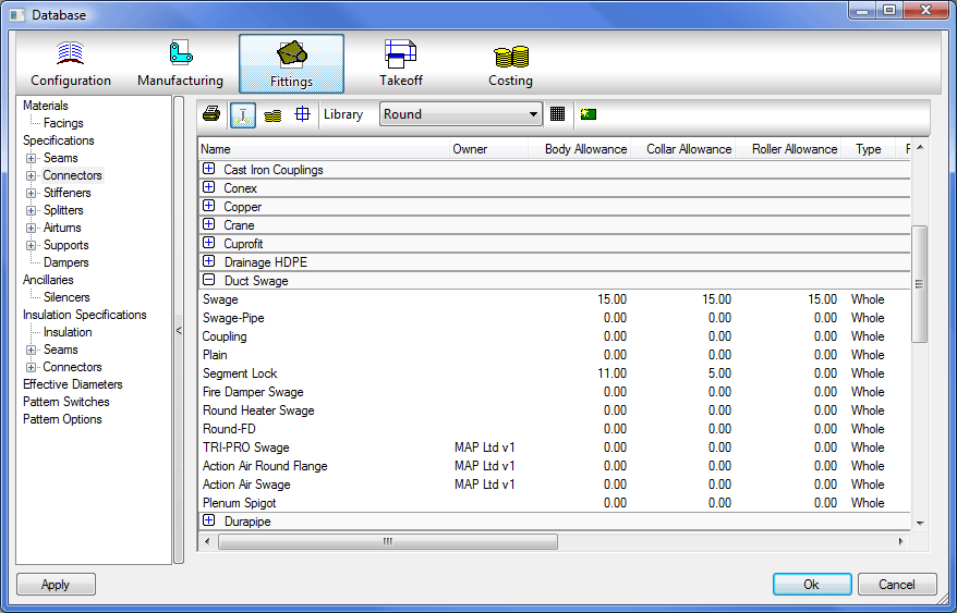
Round and Oval connectors have different fields defined.
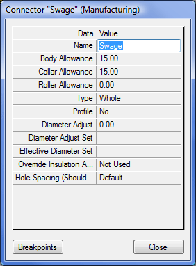
Name
Enter the name which describes the connector. Try to keep the name as short as possible since some dialogue boxes only display a limited number of characters.
Body Allowance
The allowance added to the body of the development.
Collar Allowance
The allowance added to the collar.
Roller Allowance
For oversized developments, the extra allowance on the connector to account for additional roller notching.
Type
This can be Whole (one connector per duct end) or Shared (if the connector is shared between the end pieces, and so will be one connector per every two duct ends assigned) - used primarily for producing the correct data on reports.
Profile
This will be either Yes or No, and determines whether the connector is an external (Yes) or self flange (No) for printing purposes.
Diameter Adjust
This allows the diameter of round and oval ends to be increased or decreased depending on the connector being used on the end. This adjustment is applied in addition to any other existing adjustments. For more details, see the topic Diameter Adjusts.
Diameter Adjust Set
A predefined set of parameters that are created in the can be applied to the connector using this field. These parameters are created in the Material Database and are applied to the item when the Material Specific is applied in the Diameter Adjust field.
Effective Diameter Set
This will apply predefined adjustments, to the item, that were created in the Effective Diameters table when the Use Connector Dependant Effective Diameters check box is applied.
Override Insulation Adjust
There are 2 settings that can be used. " Not Used" Will ignore this setting and apply the insulation adjustment determined in the Pattern Options - Insulation section of the Database. " Value" will allow you to override the settings applied in the insulation adjustment determined in the Pattern Options -Insulation section of the Database.
Hole Spacing Shoulder
This willl use the Value entered here as the spacing of holes from the Shoulder of the fitting, if set to Default it will use the values entered in the Pattern Options - Fixing Holes Database.
Breakpoints
Breakpoints for connectors in our software are there for the 3D viewer functionality and allow the user to control how the connector is displayed in the drawing or viewer node points are also set within the Breakpoints.