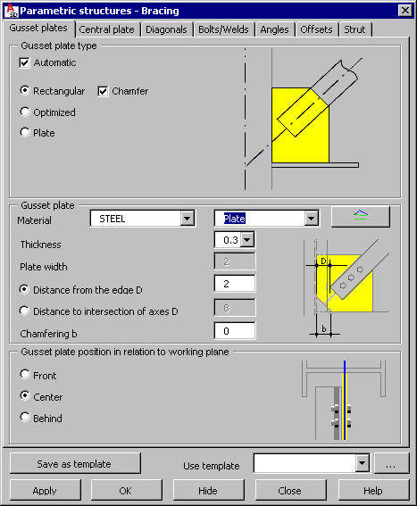
You can define geometry of steel structure bracing.
To begin defining the bracing:
- open the Parametric structures – Bracing dialog from:
- Menu: Steel > Parametric structures > Bracing
- Ribbon: ASD - Model > Parametric structures > Bracing
- Toolbar: Parametric structures > Bracing
 .
.
- In the drawing area, select the auxiliary lines of the bracing (they determine the plane in which the bracing will be positioned).
- Select two columns between which the bracing will be generated.
- Specify the limitations (elements to be considered while shaping gusset plates), such as a beam for the top limit of the bracing.
See also: Definition of bracing - principles.
Define the geometry of gusset plates at the columns:
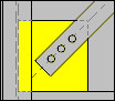 Rectangular plate
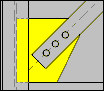 Optimized plate
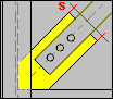 Plate
Plate
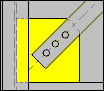
For the rectangular plate type , there is also a Chamfer option. If this option is selected, the plate will be chamfered (see the drawing below).
To generate a gusset plate automatically, select Automatic. If Automatic is cleared, all dimensions of the plate will be user-defined (edit fields for defining plate dimensions become available).
Specify gusset plate parameters:
- Material
- Family to which the plate should belong. Plate families available in the selection list are those defined in the Family Manager dialog. To add a new family to the list, click
 . The Family manager dialog displays, in which you can select a plate family.
 - Plate thickness
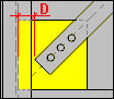
- Distance D from the edge of the bracing profile (see the drawing below)
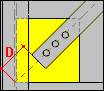
- Distance D of the bracing end to the intersection of the axes (see the drawing below)
- Value of the chamfering b - see the drawing in the dialog
- Plate width w – available only for the third type of gusset plate
In the lower part of the dialog, define the position of the gusset plate in relation to the working plane (to the axis of the column profile):
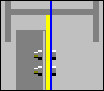 gusset plate is in front of the plane
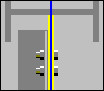 gusset plate is in the center of the plane (within the plane)
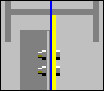 gusset plate is behind the plane
It is possible to define the Offset of the bracing plane. If an offset value differs from 0, the bracing (together with all its elements) is shifted by the given value.
After you finish defining gusset plate parameters, click the Diagonals tab to display the Bracing - Diagonals dialog.
See also: