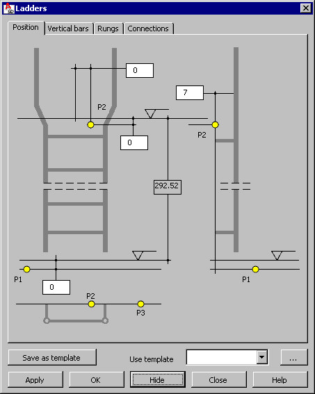
You can define geometry of steel ladders.
To begin defining a ladder, open the Ladders dialog from:
- Menu: Steel > Parametric structures > Ladder
- Ribbon: ASD - Model > Parametric structures > Ladder
- Toolbar: Parametric structures > Ladder
 .
.
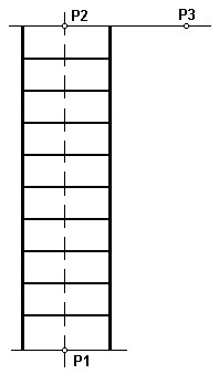
In the drawing area, click to specify the point that defines the lower floor level P1, the point that defines the upper floor level P2, and the point positioned in the ladder plane (definition of points P1, P2, and P3 displays in a schematic drawing below).
The lower and upper levels may be corrected in the dialog so that they account for the grate thickness.
All parts of a ladder are comprised in one object. Connecting elements welded to other elements of a structure to which the ladder is fixed are also an integral part of the ladder object.
A ladder consists of the following elements:
- Vertical Bars
- Rungs
- Fixing elements (angles, plates, bolts)
- Cages (see the Cages macro)
To define a ladder:
- Specify 2 points (on the lower and upper levels) that define the ladder geometry (done before the dialog displays).
- Specify structure elements to which the ladder will be fixed and levels on which fixings will be generated.
- Define parameters in the dialog.
- Accept the defined data (by clicking Apply or OK) in order to generate a ladder object in a drawing.
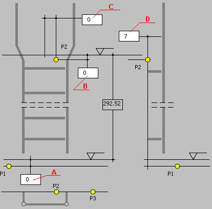
Use options on the Position tab to define parameters (see the drawing below):
- A - distance between point P1 and the lower floor level (thickness of a grate and finishing layers)
- B - distance between point P2 and the upper floor level (thickness of a grate and finishing layers)
- C - shift of the ladder axis in the horizontal direction with respect to the position of point P2
- D - distance between the ladder axis and the structure (point P2).
The difference between the floor levels is a read-only parameter in the dialog.
After you finish defining positions of the ladder elements, click the Vertical bars tab to display the Ladders - Vertical bars dialog.
See also: