Two shot injection molding is a two-step process, where both steps happen simultaneously during one cycle of the injection molding process. The Cool (FEM) analysis is also performed simultaneously on the first shot, and on the first-shot-and-second-shot combination. After the Cool (FEM) analysis is completed a Fill+Pack and a Warp analysis can also be run.
Prerequisites
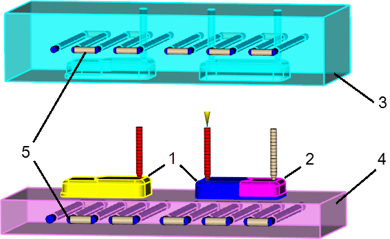
This topic assumes that you have prepared one study that includes:
- A meshed model of two identical first components, including their optional running systems (1).
Note: The runner system of the first component above the overmolding cavity (right part, not represented in the figure) is required for calculation purposes only. It has to be there but the mold must not take into account its geometry.
- A meshed model of the second component and its optional runner system (2).
- The two mold cavities, represented as
Fixed Cavity (3) and
Rotating Core (4) in the figure below.
Note: The design of the Fixed Cavity needs to take into account the runner systems represented in the figure below only.
- The cooling channels (5).
Tip: Use layers with different names in the Layers pane to separate these components.
Setup Tasks
- Open the project containing the study described previously.
- Click
 (), and select Thermoplastics Overmolding.
- Click
 () and select a sequence containing at least
Cool (FEM) + Fill + Pack + Overmolding Fill, depending whether you want the packing and warp stage included in the overmolding analysis.
() and select a sequence containing at least
Cool (FEM) + Fill + Pack + Overmolding Fill, depending whether you want the packing and warp stage included in the overmolding analysis.
- Specify the position of the first component during the first shot, and then during the second shot.
- Specify the position of the second component for the second shot.
- Identify the fixed cavity.
- Identify the rotating core.
- Set up the cooling channels.
- Make all layers visible, expect the ones containing the molds.
- Double-click Material A in the Study Tasks pane and select the material to be used in the first component Cool(FEM) and Fill+Pack analysis stage.
- Double-click Material B in the Study Tasks pane and select the material to be used in the second component overmolding stage.
Note: Alternatively, click
 and
and
 () to select the materials.
- Click
 in the study task pane, and set the injection locations for each of the first component models.
- Click
 in the study task pane, and set an injection location on the second component model.
Note: Alternatively, click
in the study task pane, and set an injection location on the second component model.
Note: Alternatively, click and
and
 () to set the injection locations.
- Click
 in the study task pane, and set the Coolant inlet parameters.
- Click
 () and specify the process settings for the first component Cool (FEM) analysis stage.
Note: The time corresponding to Injection + packing + cooling time must match the first injection only. An overmolded part is created over a double cycle: one by injection.Specify the process settings for the overmolding stage on the Wizard pages, then click Finish.
() and specify the process settings for the first component Cool (FEM) analysis stage.
Note: The time corresponding to Injection + packing + cooling time must match the first injection only. An overmolded part is created over a double cycle: one by injection.Specify the process settings for the overmolding stage on the Wizard pages, then click Finish.
The overmolding analysis is now ready to be launched.