Loads are transferred from one element to the adjacent element only if the nodes are directly or indirectly connected. Typically, the elements within one part are connected directly to an adjacent part through coincident nodes (when the meshes are matched). For linear analysis models with non-matched meshes, you can use Smart Bonding to connect parts and surfaces. Alternatively, you can run supported analysis types using the Nastran solver, which does not require matched meshes for any analysis or contact type.
How different parts in the model are connected is determined by the Contact heading in the browser (tree view). When two surfaces of different parts touch, they are connected together based on the default contact type, unless a specific contact pair is created and defined as a different contact type. See the Types of Contact page for an explanation of the available contact types and the mesh requirements.
Generate Contact Pairs
You need to create explicit contact pairs, and assign the appropriate contact type, when the default contact type is not appropriate for a pair of parts or surfaces.
Automatic Contact Pairs:
When working with a CAD model, you can choose whether the interface automatically creates the list of all contact pairs in the model, or whether you want to create the contact pairs manually. This choice is set from

 Options CAD Import tab;
Global CAD Import Options button, then set the
Automatically generate contact pairs option accordingly.
Options CAD Import tab;
Global CAD Import Options button, then set the
Automatically generate contact pairs option accordingly.
- Automatically generate contact pairs activated. When a CAD model is opened in the interface, the surfaces that are physically in contact (zero gap) are listed in the Contact branch of the browser. The contact type for each pair is Default so that they follow the setting of Contact (Default:). To set certain contact parameters to be used between specific surfaces, select the contact pair in the browser, right-click, and choose the new type of contact.
- Automatically generate contact pairs not activated. When a CAD model is opened in the interface, the time required to detect all of the surfaces that are physically in contact is not expended. You can manually choose parts or surfaces to be in contact as described next.
Add Additional Contact Pairs:
Regardless of whether the contact pairs are generated automatically or not, you can create additional contact pairs. This may be needed because you want contact between two parts (instead of between the individual surfaces on the parts), or the two surfaces are not initially in contact, or because the original entry was deleted. Also, the contact pairs in a hand-built model must be specified manually.
There are two methods to generate the additional contact pairs:
- Create pairs one at a time. This method is appropriate for CAD and hand-built models. First select two surfaces, two parts, or one surface and one part in the browser. Once they are selected, right-click the heading for one of the surfaces or parts and select the Contact command. Select the appropriate type of contact for this pair. A new heading will be created under the Contact heading in the browser for this pair. Alternatively, the parts and surfaces can be selected in the display area, then right-click and choose Contact. Normally, which entity is selected first and which is selected second does not matter, other than controlling the order of the listing in the browser. For surface-to-surface contact in a nonlinear analysis, the order may be important when defining the Contact type as Point to Surface. (See the Surface-to-Surface Contact page for details regarding surface contact in nonlinear analyses.)
- Create multiple contact pairs at a time. This method is appropriate only for CAD-based models. First select two or more parts in the browser or in the display area. Then, right-click and select
Contact
Create Contacts Between Parts. A contact pair is created for any pair of surfaces among the selected parts that are initially in contact. Each automatically generated pair is listed in the
Contact
branch of the browser. The type of contact for each pair can then be changed individually by right-clicking on the entry in the browser and choosing the desired type.
Contact between different surfaces of the same part is not supported except for surface-to-surface contact in nonlinear stress analyses. (The user interface does not prevent you from defining contact between two surfaces of the same part in a linear analysis. However, the processor will ignore the contact pair.)
Sort Contact Pairs:
When contact pairs are added to the model, they are listed in Contact branch of the browser in the order that they are created. The contact pairs are sorted whenever the model is reopened. There are three different types of contact entries:
- Part A Surface B with Part C Surface D (listed as Contact type < A/B with C/D > in the browser)
- Part A with Part C Surface D (listed as Contact type < A with C/D > in the browser)
- Part A with Part C (listed as Contact type < A with C > in the browser)
The contact pair heading in the browser lists the specified contact type (Bonded, Welded, Free/No Contact, or Surface Contact) in place of the Contact type placeholder shown in the preceding examples.
The sorting order of the contact list is by A, then C, then B, and then D (ascending).Color of Contact Pairs:
Contact pairs that are created automatically (or prior to version 23) use black text in the browser. Contact pairs that you create explicitly use blue text in the browser.
Visibility Show All Surfaces to restore visibility of the hidden parts and surfaces.
Alternatively, to view the model without shading, use
View Appearance Visual Style Edges or
View Appearance Visual Style Mesh. If model colors make it difficult to see highlighting, use
View Appearance Color By Part or
View Appearance Color By Surface to change the display. In addition, the highlight color can be set from the
Setup tab under the
Tools Options Application Options dialog.
Consider surface contact between three different parts where the different materials cause different static coefficients of friction. You must create two contact pairs and assign a unique static coefficient of friction to each pair. You cannot set the default contact type to Surface and set up two different friction coefficients.
As another example, consider a model having 50 surfaces in two different parts that interact with each other. Assume that various contact pairs have different types of contact or different contact settings. Then, selecting entries and defining or changing the contact type for each pair may be the best approach. However, if only two pairs of surfaces are in Surface Contact and the other 48 pairs of surfaces are considered to be Bonded, then you should set the default for the entire model to Bonded. Then you would select the other two surfaces pairs and create two Surface contact pairs. The idea is to minimize the number of contact pairs that must be defined. Specify the default contact type that is most prevalent within the model.
The order of the contact pairs (as listed in the Browser) affects the Model
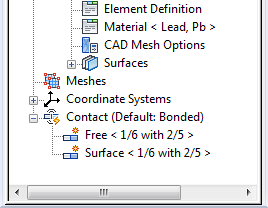
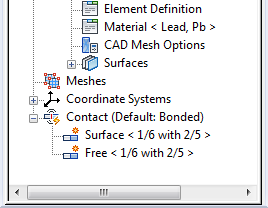
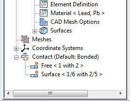
If the exact same contact pair is created (that is, a duplicate contact pair definition exists), only the first entry in the browser is used. Subsequent entries are ignored. When both part to part and part/surface are defined at the same face, the part/surface entry controls the contact type for that pair, and the other surfaces that are in contact follow the part setting. See Figure 1 for examples. Be aware that the order of the pairs may change from the order in which they are initially created. As stated previously, the contact pairs are sorted when the model is reopened. (See Sort Contact Pairs above.
|
|
| (a) The same part/surfaces are defined in contact. Free contact is the result because it is listed first | (b) The same part/surfaces are defined in contact. surface contact is the result because it is listed first. |
|

|
| (c) The contact between part 1 surface 6 and part 2 surface 5 (1/6 with 2/5) is a smaller more detailed region, so that face will have surface contact. Any other contact between parts 1 and 2 (1 with 2) will have free contact. |
(d) Same contact pairs as in example (c), but in reverse order. Since the two entries are not exactly the same, the outcome is the same as (c): part 1 surface 6 has surface contact with part 2 surface 5, and any other faces in contact between parts 1 and 2 are free. |