The FEA Editor always keeps separate vertices (duplicate vertices) at the boundaries between different parts. That is, two or more vertices exist at the same coordinate when the meshes are matched (one for each part). At these coincident vertices, the type of contact determines whether:
- the separate vertices create one node shared by the parts (bonded contact),
- two separate nodes are created but not connected together (free contact), or
- two separate nodes are created and connected together with an automatically-generated element (surface contact).
The merging of the vertices occurs when a Check Model operation is performed or at the beginning of the solution phase (Run Simulation). Depending on the analysis type, element type, contact type, and processor used to run the simulation (SimMech or Nastran), the mesh may or may not need to be matched between the contacting parts.
Mesh Requirements for Contact
The following table indicates whether adjacent parts within an assembly need to be modeled with a zero-gap fit, or if an initial gap or interference is allowed between parts for the various analysis and contact types:
| Analysis Category | Is an Initial Gap or Interference Allowed Between Surfaces? | |
|---|---|---|
| Native Simulation Mechanical (SimMech) Solver | Nastran Solver (see Note A) | |
| Linear | No. Must be zero gap, zero interference (except for Free contact). | Yes |
| Nonlinear |
Yes, for Surface and Free contact. No, for other types of contact. |
Yes |
| Thermal | No. Must be zero gap, zero interference (except for Free contact). | Yes |
| Electrostatic | No. Must be zero gap, zero interference (except for Free contact). | (not applicable) |
Note A: Nastran Welded contact supports small initial gaps. Nastran Offset weld and Surface (General), contact types support large initial gaps. Small initial interferences are permissible for all Nastran analysis and contact types. For Welded and Offset weld contact, the interference is ignored because the nodes are connected and behave as if the surfaces are bonded together. For Surface (General) contact, nodes on the slave (secondary) contact surface are repositioned to eliminate the initial interference before the results are calculated. Therefore, no interference fit reaction forces are developed. The initial interference is simply removed.
Mesh Matching Requirements when Using the Native Simulation Mechanical (SimMech) Solver
The following table indicates whether or not the meshes need to be matched between adjacent parts for different analysis and contact types when using the SimMech solver.
| Type of Contact | ||||||
|---|---|---|---|---|---|---|
| Analysis Type | Bonded | Welded | Free/No Contact | Surface Contact (see Note 4) | Edge Contact | Shrink Fit Contact |
| Linear, Static Stress | matched or unmatched (see Note 1) | matched or unmatched (see Note 1) | matched or unmatched | matched | matched | matched (see Note 5) |
| Linear, Natural Frequency (Modal) and Natural Frequency (Modal) with Load Stiffening | matched or unmatched (see Note 1) | matched or unmatched (see Note 1) | matched or unmatched | Sliding/No Separation only (matched) | not applicable | not applicable |
| Linear, Critical Buckling Load and Transient Stress (Direct Integration) | matched or unmatched (see Note 1) | matched or unmatched (see Note 1) | matched or unmatched | Sliding/No Separation only (matched) | not applicable | not applicable |
| Linear, Other | matched or unmatched (see Note 2) | matched or unmatched (see Note 2) | matched or unmatched | Sliding/No Separation only (matched) | not applicable | not applicable |
| Nonlinear | matched or unmatched (see Note 3) | matched | matched or unmatched | matched or unmatched | not applicable | not applicable |
| Thermal | matched or unmatched (see Note 1) | matched or unmatched (see Note 1) | matched or unmatched | matched | not applicable | not applicable |
| Electrostatic | matched or unmatched (see Note 1) | matched or unmatched (see Note 1) | matched or unmatched | not applicable | not applicable | not applicable |
Note 1: If you enable Smart Bonding, the mesh can be matched or unmatched. If you are not using smart bonding, then the mesh must be matched for the parts to be bonded.
Note 2: The following analysis types use the results from the modal analysis. Therefore, these analyses can take advantage of smart bonding (see Note 1) without any additional contact setup required:
- Response Spectrum
- Random Vibration
- Frequency Response
- Transient Stress (Modal Superposition)
- DDAM.
Note 3: For nonlinear analyses, the mesh can be unmatched if using Tied surface contact to perform the bonding. (The basic contact type would be Surface and the specific type of surface contact would be Tied.) If not using tied surface contact, then the mesh must be matched, and the contact type Bonded. Tied surface contact is set using the Edit Settings command from the context menu for the contact pair. See the page, Simulation Mechanical Surface Contact Options (Nonlinear) for details on Tied contact.
Note 4: For linear analyses, the Surface Contact column refers to three available contact types—Surface, Slide/No Separation, and Separation/No Sliding, all of which are selectable from the browser. Only the first type (Surface) is applicable to thermal analyses. Thermal Surface contact can optionally include thermal resistance, which results in a temperature differential between the contacting surfaces when heat is flowing. Surface contact types and options are set up differently for nonlinear analyses. Refer to the nonlinear Surface-to-Surface Contact page and its various sub-pages for more information.
Note 5: The Shrink Fit Contact column refers to two available contact types—Shrink Fit/Sliding and Shrink Fit/No Sliding. The amount of interference between parts can be represented in the CAD geometry (by overlapping the parts). Upon importation of the model into Simulation Mechanical, the surfaces are matched (zero interference, zero gap). That is, the interference is removed from the geometry and the mesh is matched between the parts. However, the amount of interference is retained in numerical form. For further discussion of this, see the Shrink Fit / Sliding and Shrink Fit / No Sliding sections below.
- A small gap in a CAD model can be removed during meshing by using the mesh matching tolerance. Removal of the gap is necessary to match the nodes. (See the Mesh Matching page.
- If a gap between parts is critical to the analysis (that is, you do not want to remove the gap), then use manually created gap elements (linear static stress) or surface to surface contact (Mechanical Event Simulation).
- Interferences between parts of a CAD assembly will be removed during CAD data importation. However, the interference is recorded numerically, as discussed in Note 5 above.
Mesh Matching is not Required when using the Autodesk Nastran Solver
Matched meshes (also referred to as conformal or continuous meshes) are not required for any analysis type or contact type when you run the simulation using the Nastran solver. For a description of the various Nastran contact types and associated parameters, please see the Nastran Contact Options page.
Choosing the Default Contact Type
The type of contact specified in the top-level Contact (Default: __) setting in the browser is applied to the model globally. The default type applies to any two contacting surfaces where an explicit contact pair of a different type has not been created (which would override the default). For example, if you can assume that all parts of an assembly are in perfect connection with each other – able to transmit all types of loads at their interface – then you can leave the default contact set to Bonded.
To change the default contact type, right-click Contact (Default: __) and choose the desired type of contact from the context menu.
Each of the available types of contact are covered in the following sections.
Types of Contact
The available contact type choices depend on the analysis type. If any of the listed contact type choices does not appear in the context menu, then that type of contact is not supported for the current analysis type.
Default:
If the Default command is selected for an explicit contact entry, then the type of contact will follow the global Contact (Default: __) setting. Default can only be selected in the browser for an existing contact pair; it cannot be selected when creating an explicit contact pair.
Bonded:
Bonded contact is applicable to all element types. The two surfaces will be in perfect contact throughout the analysis when bonded, and the loads are transmitted from one part to the adjacent part. In a stress analysis, when a node on one surface deflects, the node on the adjoining surface will deflect the same amount in the same direction. In a heat transfer analysis, the same temperature occurs in each part at the connection, and so forth.
In order to use bonded contact in models with unmatched meshes, there are two methods you can use:
- Activate Smart Bonding.
- Run your simulation using the Nastran solver instead of the native SimMech solver. Nastran contact types do not require matched meshes.
The Bonded contact type is mapped to the Nastran Welded (symmetric) contact type by default. However, you can choose among the following Nastran contact types from within the Contact Options dialog:
- Welded (symmetric), the default mapping: All slave/secondary nodes are connected to the nearest master/primary node and all master/primary nodes are connected to the nearest slave/secondary node.
- Welded (unsymmetric): All slave/secondary nodes are connected to the nearest master/primary nodes.
- Offset Weld (symmetric): Used for symmetric welded contact when there's a significant distance between the two surfaces.
- Offset Weld (unsymmetric): Used for unsymmetric welded contact when there's a significant distance between the two surfaces.
- Nastran Solver: For Nastran solutions, the term Welded Contact is analogous to Bonded Contact in Simulation Mechanical.
- SimMech Solver: For solutions run using the native Simulation Mechanical solver, the meaning is quite different. (See the Welded section immediately below.)
Welded
Welded contact is applicable only to brick and 3D element types. If the Welded option is selected, the nodes along the edges of the contact surfaces act the same as if the Bonded option had been selected. However, the nodes along the interior of these surfaces act the same as if the Free/No Contact option had been selected. This contact type simulates the connection between two parts when a weld bead is added around the perimeter of the part interface. Loads are only transmitted from one part to the other through the perimeter weld. Interior surface nodes are free to separate from, or even penetrate through, each other.
The Welded contact type is mapped to the Nastran Welded (symmetric) contact type by default. However, you can choose among the following Nastran contact types from within the Contact Options dialog:
- Welded (symmetric), the default mapping: All slave/secondary nodes are connected to the nearest master/primary node and all master/primary nodes are connected to the nearest slave/secondary node.
- Welded (unsymmetric): All slave/secondary nodes are connected to the nearest master/primary nodes.
- Offset Weld (symmetric): Used for symmetric welded contact when there's a significant distance between the two surfaces.
- Offset Weld (unsymmetric): Used for unsymmetric welded contact when there's a significant distance between the two surfaces.
Free/No Contact
Free/No Contact is applicable to all element types. If the Free/No Contact command is selected, the nodes on the two surfaces in this contact pair will not be collapsed to one node even if the mesh is matched. In a CAD model, the mesher will not necessarily force the mesh to match. These nodes will not transmit a load between the parts. In a stress analysis, the nodes will be free to move relative to the nodes on the other surface. In a heat transfer analysis, no heat will be conducted between the parts, and so forth.
Surface Contact
Surface contact is applicable only to the element types indicated below. Surface contact is available for CAD solid models, 2D created meshes, and hand-built models as follows.
- Linear static stress: You can specify surface contact between brick parts, between brick and plate parts, and between 2D parts. When you run a simulation using the native Simulation Mechanical (SimMech) solver, contact is created only if the gap between the parts is zero. The meshes do not have to match when you plan on using the Nastran solver to run the simulation.
If the Surface Contact command is selected, and the meshes are matched, a zero-length contact element (similar to a user-created gap element) is placed between the nodes. The nodes are free to move away from each other, but the nodes cannot pass through each other when they come into contact. Imagine a very small line created between the nodes on these surfaces. If that line becomes longer during the analysis, it will have no effect on the model. If that line becomes zero length, it will act as a spring with a stiffness value that will resist this motion.
When using Surface Contact, the analysis involves an iterative process; hence, the analysis takes longer to run than an analysis with bonded contact. This process is used to determine if the deflection due to the loading causes each pair of nodes on the surfaces to be in contact or not.
Note: For additional modeling information related to contact elements in a linear stress analysis see Perform Analyses with Gap Elements.When the contact elements are defined for surface contact pairs, a direction is calculated for each contact element. For solutions run using the native Simulation Mechanical solver, you can control the method used for calculating this direction. In addition, friction can be included for applicable types of contact. Please see the Friction Tab section of the Simulation Mechanical Contact Options page for more information. For Nastran solutions, see the General Tab section of the Nastran Contact Options page for information concerning friction and other contact parameters.
Contact in Static Stress with Linear Material Models analyses assumes that the contact force is transmitted through the same set of nodes as originally in contact, and the direction of the force is the same as the original normal direction. That is, the deflection does not change the points in contact or the direction (small deformation theory).
- Mechanical Event Simulation and nonlinear stress: You can specify contact between combinations of brick, shell, 2D, beam, and truss parts. Surface contact in nonlinear analyses is defined differently from surface contact in linear analyses. Because nonlinear analyses can calculate large deflections, the parts do not need to be physically in contact initially in order to create automatic contact.
The contact parameters in a Mechanical Event Simulation or nonlinear static stress analysis are entered in the Contact Options dialog. This dialog, and the various options it contains, are very different from the contact settings for linear, thermal, and electrostatic analyses. Additionally, both static and sliding (dynamic) friction can be included in a nonlinear analysis. (For details, see the Surface-to-Surface Contact page and its various sub-pages.)
- Heat transfer analyses: You can specify surface contact between brick parts, between brick and plate parts, between plate parts, and between 2D parts. For solutions run using the native Simulation Mechanical (SimMech) solver, automatic contact is created only if the initial gap between the parts is zero. The meshes do not have to match when you plan on using the Nastran solver to run the simulation.
Surface contact in a thermal analysis creates a zero-thickness 2D or 3D element between the surfaces. Since the nodes on the two parts are not merged together, there can be a temperature gradient across the joint whenever there is heat flux across the contact area.
For a thermal analysis, you can define the contact resistance for any surface contact pair. Use this resistance to simulate the imperfect thermal conductance across the contact region and the resulting temperature differential between the contacting surfaces. You can also use this resistance to simulate a thin film between two parts, such as an electrical insulator. See the Thermal Tab section of the Simulation Mechanical Contact Options page for more information. For Nastran solutions, see the Advanced Tab section of the Nastran Contact Options page for information concerning thermal contact conductance and other contact parameters.
Thermal Contact Example
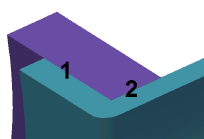
Contact elements are not created at boundaries where two parts with surface contact are bonded to a different part (or multiple parts). For example, imagine parts 2 and 4 are defined as surface contact with each other and bonded to part 1. See Figure 10(a). A detail of the joint shows that parts 2 and 4 are separated from each, and the gap is filled with an 8-node thermal contact element (for 3D models) or 4-node thermal contact element (for 2D models). See Figure 10(b). However, no contact element is created at the location where parts 2 and 4 are bonded to part 1.
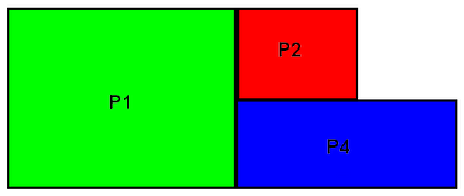
(a) Example three part model. Parts 2 (P2) and 4 (P4) have surface contact defined between them. Both are bonded to part 1 (P1).

contact element

(b) Detailed view of the contact between the parts. Thermal contact elements are create everywhere except for the element in contact with part 1 because of the bonding. Thus, the contact area between parts 2 and 4 is smaller than ideal. (The gap between parts 2 and 4 is exaggerated for clarity. No gap is created in the analysis.)
Figure 10: Example Thermal Contact Tip: A thermal resistance of 0, indicating a perfect contact between the parts, is not a good choice. A resistance of 0 implies a conductance of infinity, which leads to inaccuracies during the numerical solution. Use a small, nonzero value to simulate such conditions when they exist.
By default, Surface contact maps to the Nastran General (Symmetric) contact type. Alternatively, you can choose the General (unsymmetric) type within the Contact Options dialog.
Sliding / No Separation
Bonds contact surfaces in the normal direction while allowing the surfaces to slide relative to each other in the tangential direction.
By default, Sliding / No Separation contact maps to the Nastran Slide (Symmetric) contact type. Alternatively, you can choose the Slide (unsymmetric) type within the Contact Options dialog.
Separation / No Sliding
Contact surfaces can partially or fully separate in the normal direction, but cannot slide relative to each other in the tangential direction.
By default, Separation / No Sliding contact maps to the Nastran Rough (Symmetric) contact type. Alternatively, you can choose the Rough (unsymmetric) type within the Contact Options dialog.
Edge Contact (SimMech Solver Only)
If the Edge Contact command is selected, the nodes along the edges of the contact surfaces act the same as if the Surface Contact command had been selected. The nodes along the interior of these surfaces act as if the Free/No Contact command had been selected. In other words, contact only occurs around the perimeter of the contact area, at the edges of the surfaces.
Edge Contact is not supported for simulations run using the Nastran solver.
Shrink Fit / Sliding (SimMech Solver Only)
Behaves like Surface Contact but with initial interference between the contacting parts. The amount of interference (intensity of fit) can be determined automatically from the CAD geometry or you can specify it manually. Optionally, you can include friction between the contact surfaces. For more information on the applicable contact settings, see the Shrink fit Tab section of the Simulation Mechanical Contact Options page.
Shrink Fit / Sliding contact is not supported for simulations run using the Nastran solver.
Shrink Fit / No Sliding (SimMech Solver Only)
Behaves like Separation / No Sliding contact but with initial interference between the contacting parts. Use this option when the intensity of fit and friction are great enough to prevent relative motion (sliding) between the contacting parts. The radial interference is specified automatically (CAD-based) or manually in the same manner as it is for Shrink Fit / Sliding contact. For more information, see the Shrink fit Tab section of the Simulation Mechanical Contact Options page.
Shrink Fit / No Sliding contact is not supported for simulations run using the Nastran solver.
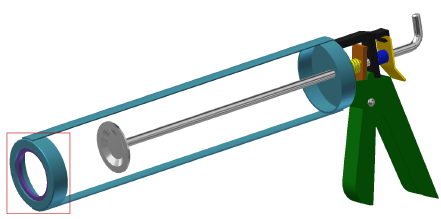
Example
- The contact type for interface 1 is Surface Contact. The contact does not constrain the ring from moving in either the normal or tangential directions.
- The contact type for interface 2 is Shrink Fit / No Sliding. The contact has an initial interference fit as the outer diameter of the ring is larger than the inner diameter of the frame. However, the ring is still free to move in the normal and tangential directions if the friction force from the shrink fit is overcome.