To edit transition points
- Draw the duct in 2D. See To Lay Out Underground Design Features.
- On the command line, enter AUDTRANSITIONPOINT to open the
Transition Points palette.
Each row in the Transition Points palette represents one transition point. The ID column indicates the sequence of transition points.
- Select the segment that represents the duct.
Transition point information is displayed in the palette. By default, the start and end points of the duct are provided. The following steps can be done both in 2D or 3D mode.
- To add transition points to the segment/duct, use either of the following methods:
- Click Invoke AudTransitionAdd Command
 . Click to specify a point on the duct.
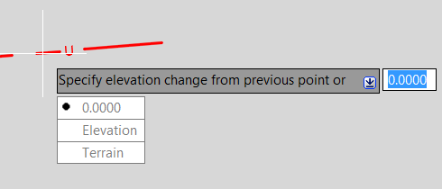
Enter the elevation change from the previous point or choose one of the following options: Click 0.0000 to specify no change in elevation from the previous point. Click Elevation and enter the exact elevation of the new transition point. Click Terrain to specify the elevation change based on the insert point's elevation on the terrain.
- Click a row in the Transition Points palette. Click Add Transition Point
 .
.
A new transition point is added at the midpoint between the selected transition point and the previous transition point. Edit the values of the new transition point.
- Click Invoke AudTransitionAdd Command
- Elevation: The absolute elevation of the transition point. You can edit this value for each manually created transition point. For start and end points, if there is a connected structure, the value is the Z value of the connected structure.
- Angle: The angle at the transition point. It is calculated internally for manually added transition points so they cannot be edited. You can edit the angle value for start and end points. The edited value is used for vertical sweep generation.
- Radius: The radius of the sweep at the transition point. This value is read-only.
- Projection Length 3D: The distance projected to the X-Y plane from the virtual start point to the transition point. This is read-only for start point, end point, and horizontal bends. You can edit this value for manually added transition points.
- Projection Length 2D: The distance from the 2D start point to the transition point. The system use 3D geometry for calculating, so for some case, the Transition Point may not project in the 2D line, the system will use NaN (Not a Number) to describe it.
- Reversed Projection Length 3D: The distance from the end point to the transition point. It equals to 3D length minus Projection Length 3D.
- Reversed Projection Length 2D: The distance from the 2D line's end point to the transition point. It equals to Length of the line minus Project Length 2D.
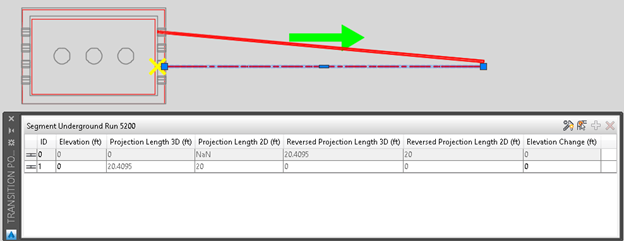
For example, an Underground line connects to a Vault with 20ft long as below:
- The Yellow x is the Transition Point of the line's start point, it did not project in the 2D line, so Projection Length 2D for the first Transition Point is not a number.
- If you change any project length value of a Transition Point, the other three will be changed automatically and the Transition Point will be moved to new place.
- Terrain Offset: The relative elevation based on the point's elevation on terrain where the transition point is placed. The value reflects the results of the AUDTRANSITIONADD Terrain option.
- Elevation Change: The relative elevation based on the previous transition point's elevation. The value reflects the results of the AUDTRANSITIONADD 0.0000 option.
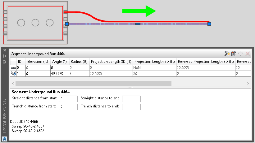
Transition Points Palette
When you click a row in the Transition Points palette, the corresponding transition point is highlighted in the canvas. If there are sweeps at the transition point, they are listed.
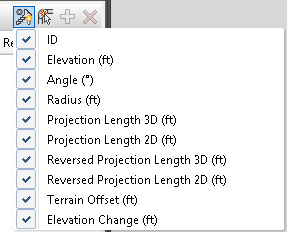
To set the visibility of the columns, click Select visible columns
 and select the columns to display.
To model the transition from structure layout to trench layout
In many cases, a duct exiting a structure will follow a straight path for a given distance before a transition is begun where it shifts to the trench layout. To model this, 4 rule points are added under Rule Configuration/Underground/Equations to define the distance of auto-transition point where structure layout switches to trench layout.
- Straight distance from start: A distance for which the duct exits straight from the port of the segment's starting structure.
- Straight distance to end: A distance for which the duct exits straight from the ports of the segment's ending structure.
- Trench distance from start: A distance from the start straight section's endpoint to where the duct begins following the trench layout segment ports.
- Trench distance to end: A distance from the end straight section's endpoint to where the duct begins following the trench layout segment ports.
These values will be applied to all the segments in the drawing. They can also be edited in the Transition Points palette for an individual segment.