- Click Configuration tab
 Data panelBase MapConvert To Model Data.
 - In the Convert to Industry Model dialog box, under Source Data, click any of the following:
- Add File-based Sources To Convert
 . Use this option to convert data from DWG, SDF, SHP, and SQLite sources to design features.
 - Add Industry Model Sources To Convert
 . Use this option to convert data stored in AutoCAD Map 3D. In this case, minimal mapping is needed.
 - Add FDO Connection Sources To Convert
 . Use this option to convert data from an FDO connection to design features. You must first connect to the source using Configuration tabData panelAdd Base Map Connection.
 - To use a saved mapping file, click Load Mapping From File and specify the mapping file.
- Add File-based Sources To Convert
- To apply a filter to the source data, right-click the source and click Filter Source.
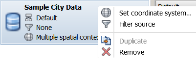
- If necessary, you can change the coordinate system assigned to the source data. Right-click the source and click Set Coordinate System. Note: You must specify the original coordinate system for the data. Do not specify the coordinate system for the design drawing - the application transforms the data to the target coordinate system when it adds it to your design. For more information, see the AutoCAD Map 3D Help.
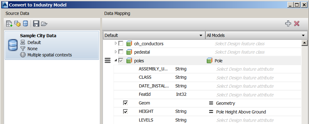
- In the Data Mapping area, define the mapping between items in the source data and feature classes and attributes in the Utility Design drawing.
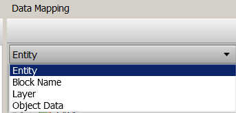
If the source is DWG, you can create mappings from entities, blocks, layers, or object data, to corresponding feature classes in the industry model. From the drop-down list, select Entity, Block Name, Layer, or Object Data.
- You can also create mappings between particular attribute values.
You can specify the how attribute values in the source data map to values in the design. For some attributes, you can use the Expression Builder when mapping attribute values. For example, you can convert units, perform calculations, or concatenate values in the source when mapping to attribute values in the design. For DWG files, you can map colorindex, linetype, and lineweight values in the source data to the appropriate values in the design drawing. For example, linetypes in a DWG might represent conductor models in the design drawing.
You can also map domain values in the source to corresponding domain values in the target if the target attribute is a domain type attribute (any attribute for which the value is a domain value such as Status) or the target attribute is Model Name. For more information, see To Map Domain Values.
- When you have completed the mapping for a source, you can save the mapping to a file. You can later reload the mapping file for future conversions. Click Save Mapping To File.
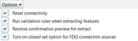
- Select any of the following options:
- To establish connectivity between features within the Automatic Connection Tolerance range, select Options Reset Connectivity.
For more information on setting the Automatic Connection Tolerance, see General Layout Options.
- To run design validation rules, select Options Run Validation Rules When Extracting Features.
Errors are displayed in the Validation Results palette of the Dashboard when the source data is converted.
- To display the number of features that will be converted before beginning the process, select Options Receive Confirmation Preview for Extract.
- To include contained features during extract and merge, even if they do not fall within the specified geometric filter, select Options Turn On Closed Set Option for FDO Connection Sources.
For example, you might have a pole with a contained transformer. Even if the pole and transformer do not share geometry, you can preserve the containment relationship during extract and merge. For more information on extract and merge, see To Extract and Merge Data.
- To establish connectivity between features within the Automatic Connection Tolerance range, select Options
- When you have finished creating the mapping between the source and the Utility Design industry model, click Convert.
Only mapped items are converted. If you do not want to convert a mapped item, clear the checkbox for that item.
Note: The Extract Existing dialog box provides a count of the number of features that will be converted. Converting many features can take a long time. Be sure to convert only the features you need. If necessary, click Cancel and make adjustments in the Convert to Industry Model dialog box to reduce the number of features being converted.