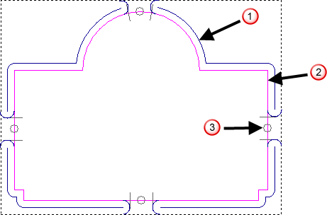
Bridging is a precautionary measure to prevent profiled vector artwork from shifting in the material block as it is machined. Bridges exist on the vector rather than on the toolpath, and you can add bridges to the vector, either before, during, or after calculating a profile pass.
The cutting tool used to profile vector artwork lifts slightly in the Z direction about the position of each bridge, leaving small tabs that hold the machined vector artwork in position during machining. The machined vector artwork can then be gently snapped from the material block.
 Toolpath
 Vector
 Bridge location
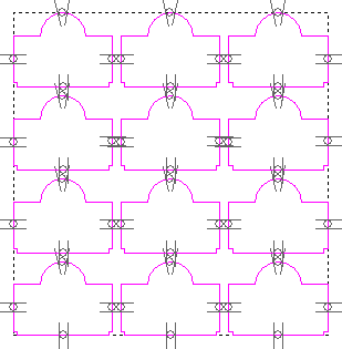
Bridges remain associated with the vector even after the vector has been transformed. In the following example, four bridges are added to a simple vector. The vector is then resized and copied. You can see that the bridges on the original vector are replicated on each copy.
|
Before |
After |
|
|
|

There are two methods you can use to add bridge locations to a vector:
- Use the Add Bridges option on the Profile, Bevel Carving, Female Inlay, Male Insert, or 3D Cut Out panels; or
- Use the Create Bridges tool on the Toolpaths panel.
After you have added the bridges, you can edit them individually, or simultaneously.