Use the options in the Profiling Tool area to specify the tool you want to use, the cutting direction, and whether you want to include lead-in moves, lead-out moves, ramping moves, and bridges:
- Click to Select — Click the control bar to select the tool you want to use using the Tool Database dialog. When you select the tool, click the control bar showing the name of the tool to display its parameters. To change the selected tool, click Select. To deselect the selected tool without choosing a replacement, click Deselect.
- Cutting Direction — You can control the cut direction of the tools used for machining by selecting either conventional or climb milling.
- Climb — Select the option to rotate the cutter in the same direction as the feed motion. The option is selected by default.
- Conventional — Select the option to rotate the cutter in the opposite direction to the feed motion.
Tip: Set the default cutting direction on the Options panel. - Add Lead In / Out Moves — Select the check box to add lead-in and lead -out moves to the toolpath. Lead-in and lead-out moves are used to prevent the tool from marking the final profile when it first comes into contact with the profile, and at the end when it leaves the profile.
- Do not lead out — Select the check box if you only want to have a lead-in move.
- Distance — Specify the distance in the toolpath at which you want the profiling tool to cut into and retract from a vector's boundary.
- Over cut — Specify the distance from the start/end point in the profile pass that you want the profiling tool to machine beyond. This further helps to create a smooth finish.
Choose an option to specify how you want the tool to move:- Linear — Select this option to instruct the profiling tool to lead into and out of a vector's boundary in a straight-line motion. Enter values in the
Angle in and
Angle out boxes to specify the angle of the linear lead-moves.
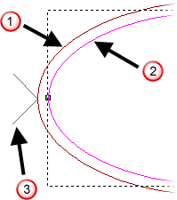
 Toolpath
 Vector
 Lead-in/out moves
- Circular arc — Select this option to instruct the profiling tool to lead into and out of a vector's boundary in an arc motion. Enter a value in the
Radius box that is equal to or greater than the
Distance to specify the radius of the arc.
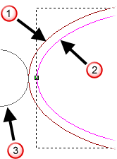 Toolpath
Vector
Lead-in/out moves
Toolpath
Vector
Lead-in/out moves
When editing lead moves associated with a profile pass used to machine inside of a vector, the distance of a linear lead move or the radius of a circular arc move is considered.
When adjusting the position of a linear lead move, ArtCAM checks to ensure the distance of the lead move remains within the boundary of the profile pass. If the current distance of the lead move intersects with the profile pass, its distance is cropped so that it does not.
When adjusting the position of a circular arc lead move, ArtCAM checks to ensure the radius of the lead move remains within the boundary of the profile pass. If the current radius of the lead move intersects with the profile pass, the lead move is instead converted to a linear move with a distance that does not.
- Automatic Positioning — Select this option if you want to position the lead-in and lead-out moves at the optimum point in the vector, which is usually within its longest linear span. Deselect this option if you want to position the lead-in and lead out moves at the vector's Start Point.
Note: The Automatic Positioning option should not be selected if you want to use the Lock Start Points option for toolpath sequencing.Note: If you want to reposition the lead-in and lead-out moves, you can change the Start Node.
- Cutter compensation — Select this option if you are creating a new toolpath and want to apply cutter compensation commands (G41 - comp left and G42 - comp right) to the NC code associated with the profile's start and end point. Cutter compensation enables your machine tool's controller to calculate the offset toolpath based on the profile that is specified in the NC code. The offset value is typically stored in the controller's memory. The main advantage of this approach is that changes to the offset value are completed on the machine without editing the NC code. This is practical when making adjustments to compensate for tool wear or changing to a tool with different diameter.
- Add Ramping Moves — Select the check box to add ramping moves to the toolpath, then select the ramping move option you want to use:
- Spiral — Select this option to descend in a helical ramp motion around the profile's perimeter.
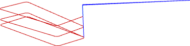
- Zig-Zag — Select this option to descend in linear zig-zag moves with a specified Z angle and distance.
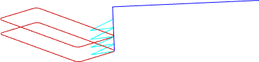
If you select Zig-Zag, you can select and specify the following values:
Max Ramp Angle (A) — Enter the maximum angle of descent for each zig and zag movement of the profiling tool.Note: The ideal ramp angle is between 0 and 20 degrees from the table surface. This angle enables the tool to enter the material block at 100% of the feed rate. At angles greater than 20 degrees, you should reduce the feed rate.Max Ramp Length (L) — Enter the maximum distance that you want the profiling tool to zig-zag across the material surface.
Min Ramp length (Lmin) — Enter the minimum distance that you want the profiling tool to zig-zag across the material surface.
Zig Start Height (S) — Enter the height at which the ramping moves start.
- Smooth — Select this option to add a short linear ramp to each toolpath segment.
If you select Smooth, you can select and specify the following values:
Max Ramp Angle (A) — Enter the maximum angle of descent for each zig and zag movement of the profiling tool.Note: The ideal ramp angle is between 0 and 20 degrees from the table surface. This angle enables the tool to enter the material block at 100% of the feed rate. At angles greater than 20 degrees, you should reduce the feed rate.Max Ramp Length (L) — Enter the maximum distance that you want the profiling tool to zig-zag across the material surface.
Min Ramp length (Lmin) — Enter the minimum distance that you want the profiling tool to zig-zag across the material surface.
- Spiral — Select this option to descend in a helical ramp motion around the profile's perimeter.
- Add Bridges — Select the check box to add bridges to the vectors you are using to create the toolpath. Bridging is a precautionary measure to prevent profiled vector artwork from shifting in the material block as it is machined.