Shows 3D objects and slices
The display occupies the biggest section of the user interface. It provides the 3D visualization of a project, including parts and the platform. The style of visualisation may adjust if the currently performed task requires it, such as when making repairs.
The display is also used to show slice contours and hatches.
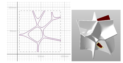
Left: The two-dimensional view on the slice of a part in the slice commander. Right: A part in the repair module.
Auxiliary Display Elements
In addition to the visualization of part, project, or slice, the display provides further useful elements:
- Ruler
- Perspective indicator
- Status bar
Rulers
Rulers provide a visual cue as to the current scale of the display. They are scaled dynamically with the zoom.
Netfabb provides
 two rulers, a horizontal one at the bottom, and a vertical one along the left, and using the options
System > Settings > Display >
two rulers, a horizontal one at the bottom, and a vertical one along the left, and using the options
System > Settings > Display >  Ruler, you can configure their color and visibility, and also toggle the vertical one of the rulers.
As you zoom, the rulers adapt to illustrate the display scale.
Perspective Indicator
To give an indication of the viewing angle relative to the build platform (read: the global coordinate system), a representation of the coordinate system is available in the bottom-left corner. It shows the three cardinal axes as well as the three planes formed between them. To help recognizing the orientation, not only are they colored the same as the axis that stands vertically upon them (X axis - YZ plane - blue, Y axis - XZ plane - orange, Z axis - XY plane - green), they are also adjusted in size. The further the planes are away from the camera, the bigger they are drawn.
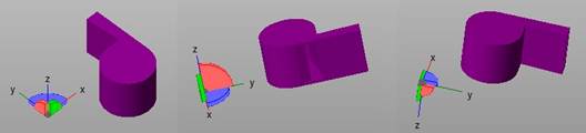
Three different perspectives and the perspective indicator in the matching orientation.
Status Bar
The status bar lists several items of information such as:
- Buildspace size
- Actions currently available through the left mouse button as well as text describing them
- A progress bar for actions that do not have a progress indicator of their own