Options and their function explained
- Cluster Detection
- Edge with Polyline Support
- Area with Volume Support
- Area with Bar Support
- Area with Polyline Support
- Down-oriented Point Bar Support
- Surround Volume by Polyline
- Skeleton with Polyline
 Delete support
Cluster Detection
| Parameter | Description | Notes |
|---|---|---|
|
Critical angle |
Measured between the horizontal and the surface of down-facing triangles, this angled area must be, and at minimum will be, supported. Adjust this to meet your machine's and material's requirements. |
0-90 ° |
|
Noncritical angle |
Measured between the horizontal and the surface of down-facing triangles, this angled area highlighted in yellow can be used to widen the cluster area beyond the critical angle, to smoothen the support contour or to merge critical clusters. |
0-90 ° |
|
Minimal, Maximal area |
A detected cluster's area must be fully within the range specified here, or it will be disregarded for the respective support action. |
|
|
Cluster type |
The Type classifies clusters by the angle between triangle normals along their borders. If more than 75 % of a cluster's border length is formed by bordering triangles with converging normals, a cluster is considered concave. If more than 75 % of bordering triangles have diverging normals, the cluster is considered convex. In between, they are considered neither.
Tip: To restrict supporting to those areas which are neither convex nor concave, support the convex and concave ones first and follow up with a catch-all while disallowing duplicate support.
|
All, Concave, Convex, Non-concave, Non-Convex |
|
Cluster inside or outside |
Clusters are considered inside when they belong to a fully enclosed cavity (a hollowing shell) with no connection to the outer skin. |
All, Inside, Outside |
|
Duplicate support |
The sharper the angle of the support area, the less support is needed there. This sets whether areas which need more support (flat angle) should get the support twice. |
No, Yes |
|
Keep distance to support |
When creating supports next to other, existing supports, it may be set to keep a distance between. |
No, Yes |
|
Distance to other support |
When distance to other supports is requested, this amount will be kept as the distance. |
|
|
Minimal, Maximal area above part |
A detected cluster's down-projected area must only be intruded into by other mesh (same or different part) to a fraction specified by this range, or it will be disregarded for the respective support action. |
0-100 % |
|
Minimal, Maximal z height |
Any point in a detected cluster's area must lie within the z height range specified here, or the entire cluster will be disregarded for the respective support action. |
0-10,000,000 mm |
|
Respect CAD face groups |
When a cluster is found to intersect with one or more face groups, every section thus created is handled as if it was a separate cluster. |
No, Yes |
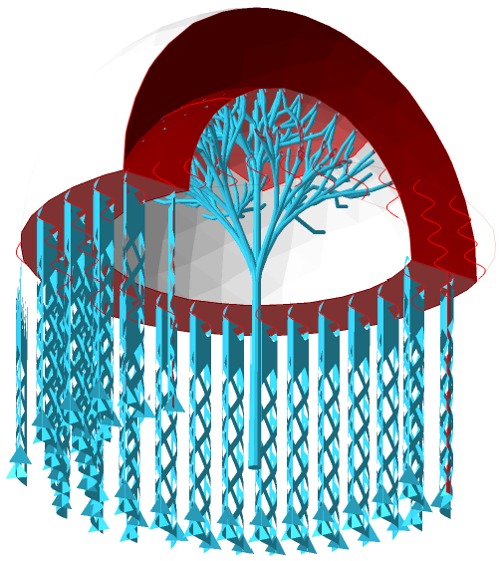
The figure displays a half-cut hollow sphere which contains a concave and convex cluster. A script can include several cluster types with different actions, like polyline supports or bar supports.
Edge with Polyline Support
| Parameter | Description | Notes |
|---|---|---|
|
Minimal, Maximal edge length |
Edges beyond the range of lengths specified here will be disregarded for applying supports. |
|
|
Maximal polyline curvature |
Sets the curvature of a polyline may have at most. If this maximum value is exceeded, a new polyline begins. |
0-180 ° |
|
Maximal edge angle to XY-plane |
Describes the maximum angle between an edge and the XY-plane. If the maximum angle is exceeded, the edge is disregarded for applying supports. |
0-90 ° |
|
Create anchor on curvature |
Defines on which curvature of the edge a new anchor point will be added. The anchor points will be created around the edge. |
0-180 ° |
|
Neighbor area angle |
0-90 ° |
|
|
Anchor distance |
Sets the distance between two anchor points. |
1-100 mm |
|
Contour offset |
Sets the distance between an anchor point and a clear area. |
0-5 mm |
|
Startpoint distance |
Sets the border distance between the edge and the start of the support structure |
0-5 mm |
|
Enhancement lines per side |
Adds additional polyline supports parallel to edges for reinforcement. |
0-5 |
|
Distance of enhancement |
The additional parallel polyline supports will be this far apart. |
0.01-10 mm |
|
Support properties |
See Polyline Supports reference. |
Area with Volume Support
| Parameter | Description | Notes |
|---|---|---|
|
Cluster |
Refer to the Cluster Detection section. |
|
|
Contour accuracy |
Specifies maximum permissible deviation when following a contour |
0.01-0.50 mm |
|
Contour offset to wall |
The anchor points along the contour can be moved further apart from the edge. The offset describes the distance from the edge to the next wall. |
0.01-5.00 mm |
|
Free contour offset |
Describes the distance between an anchor point and the next edge. |
0.01-5.00 mm |
|
Support properties |
See Volume Supports reference. |
Area with Bar Support
| Parameter | Description | Notes |
|---|---|---|
|
Cluster |
Refer to the Cluster Detection section. |
|
|
Anchor distance |
Defines the space between two anchor points or bars. |
|
|
Anchor alignment |
Switches between rectangular and hexagonal anchor placement. |
|
|
Contour offset to wall |
Anchors will keep a distance from a cluster contour that borders a wall (a concave border). |
|
|
Free contour offset |
Anchors will keep a distance from a cluster contour that does not border a wall. |
|
|
Connection to bouquet-structure |
When active, bars are merged into trunks before reaching their lower end on part or platform. |
|
|
Diameter of bouquet-structure |
Defines the maximum diameter of the whole bouquet structure. Smaller diameters cause creation of more, and smaller, bouquets. |
|
|
Height of bouquet-structure |
Describes the distance between the first branch of a bouquet structure and the part. |
|
|
Recursive depth of bouquet-structure |
Sets the limit of branches per bar between the first branch and the part. |
|
|
Project bar to platform |
If the point directly vertically underneath an anchor is not on the platform, Netfabb will attempt to angle (up to a specifiable threshold) and pan the bar to find a way that does terminate on the platform. If no suitable angle or panning can be found, the bar will be projected vertically as usual. |
|
|
Support properties |
See Bar Supports reference. |
Area with Polyline Support
| Parameter | Description | Notes |
|---|---|---|
|
Cluster |
Refer to the Cluster Detection section. |
|
|
Anchor distance |
The detected area will supported with polylines. The anchor distance defines the space between two anchor points for each polyline. |
|
|
Hatch distance |
Sets the distance between two polylines. |
|
|
Rotate by Z |
Rotates the arrangement of the polylines by the entered value. |
|
|
Wave amplitude |
Defines the distance between every intermediate anchor point from a polyline. A value >0 creates a wave (if polyline is smoothed) or a zig zag pattern (if polyline is not smoothed). |
|
|
Support properties |
See Polyline Supports reference. |
Down-oriented Point Bar Support
| Parameter | Description | Notes |
|---|---|---|
|
Cluster |
Refer to the Cluster Detection section. Results of cluster detections are the blunt tips you may filter for with the switch Supported tip shape. |
|
|
Anchor distance |
Sets the distance between two anchor points or bars. In this way, support between two bars close to each other can be avoided. |
|
|
Supported tip shape |
Both single vertices ("sharp tips") as well as convex clusters ("blunt tips") may be eligible for receiving bar support. With this switch, you can restrict bar support creation to either of them. |
All, Sharp, Blunt from cluster detection, Sharp outside cluster. |
|
Support properties |
See Bar Supports reference. |
Surround Volume by Polyline
| Parameter | Description | Notes |
|---|---|---|
|
Minimal, Maximal edge length |
Edges beyond the range of lengths specified here will be disregarded for applying supports. |
|
|
Border type |
The settings help to prevent the polyline from merging with any part wall, if it’s set to free border. Border to wall will only place polylines when there is a wall next to the edge. |
All, Free border, Border to wall |
|
Contour type |
The action can also be performed on inner contours where it is not the outer edge of the cluster. |
All, Inner contour, Outer contour |
|
Support properties |
See Polyline Supports reference. |
Skeleton with Polyline
| Parameter | Description | Notes |
|---|---|---|
|
Cluster |
Refer to the Cluster Detection section. |
|
|
Minimal edge length |
Defines the distance between the contour and the volume supports that is needed for a polyline to be created. |
|
|
Contour offset to wall |
The anchor points along the contour can be moved further apart from the edge. The offset describes the distance from the edge to the next wall. |
|
|
Free contour offset |
Describes the distance between an anchor point and the next edge. |
|
|
Support properties |
See Polyline Supports reference. |
Delete support
| Parameter | Description | Notes |
|---|---|---|
|
Above z value |
Supports entirely above this value will be deleted. |
|
|
Below z value |
Supports entirely below this value will be deleted. |
|
|
Entity type |
Restricts the support deletion to the desired type. |
All, Entity bar, Entity polyline, Entity volume. |