Controls to modify density map data manually, and how to use them
Density Map Controls
Editing the density map is done by a control element that can be moved around the build platform:
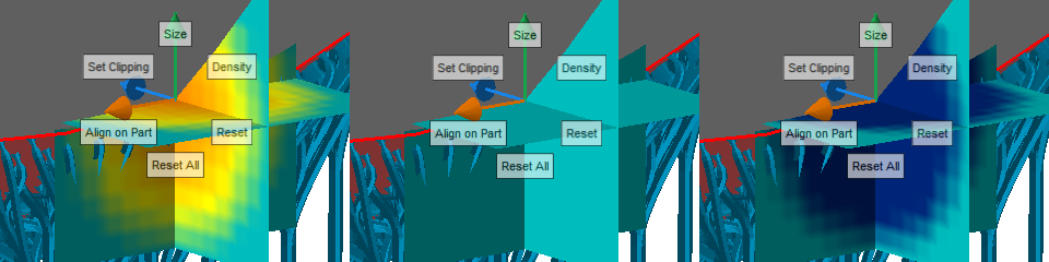
Use these controls to modify the density map. The three panes show a color-coded cross section of the volumetric map at its current location. Teal color represents zero density change, yellow and red an increase, and blue a decrease in density.
To use this element you must have the part loaded in the support module. In the toolbar, click
 Edit density map.
|
Size |
Offers a slider to modify the size of the volume affected by any change. |
|
Density |
Provides a slider to modify the local density change information. Releasing the slider applies the change immediately, and any affected supports are recalculated. |
|
Reset |
Resets the local map volume to no change. |
|
Reset All |
Resets the entire map to no change. |
|
Align on Part |
Click this button once, then once somewhere on a part to put the control's center on the part surface. |
|
Set Clipping |
Moves the clipping planes such that they intersect at the center of the controls. Note: You will have to activate the clip highlighting and section transparency yourself.
|
To Move the Density Map Controls
The control can be moved in multiple ways:
- To move the controls along one of the cardinal axes, click and hold to grab one of the directional arrows, then drag the mouse. Release the mouse button once the controls are placed at the desired location.
- To move the control parallel to the display, click and hold to grab the teal planes, then drag the mouse. Release the mouse button once the controls are placed at the desired location.
- To place the control's center onto a part's surface, click Align on Part, then click on the part at the desired location.
To Modify a Density Map Locally
Click and hold Density, then move the mouse to move the appearing size slider. Release the mouse button once the desired density change is reached to apply the modification.
To Adjust the Volume of Effect
Changes to the density map are applied over the size visualized by the three teal planes. The actual change is a spherical volumetric hotspot in the center of the three planes.
Click and hold Size, then move the mouse to move the appearing size slider. Release the mouse button when the desired size is reached.
To Reset a Density Map Locally
Place the density controls at the location where you want to reset the map, then click Reset.
To Reset the Entire Density Map
Click Reset All to reset the entire density map for the current part to no change regardless of the control's current location.