Editable Patch provides controls for manipulating an object as a patch object and at five sub-object levels: vertex, handle, edge, patch, and element.
-
Create or select an object >
 Modify panel > Right-click object's entry in the stack display > Convert To: Editable Patch
Editable Patch objects provide the same basic functionality as the Edit Patch modifier. Because working with them requires less processing and memory, we recommend you use Editable Patch objects rather than the Edit Patch modifier whenever possible.
When you convert an object to Editable Patch format or apply an Edit Patch modifier, 3ds Max converts the object's geometry into a collection of separate Bezier patches, each patch made up of a framework of vertices and edges, plus a surface.
- The framework of control points and connecting tangents defines the surface. Transforming the components of this framework is the primary technique in patch modeling. The framework does not appear in scanline renderings.
- The surface is the Bezier patch surface, whose shape is controlled by the vertices and edges. The surface is the renderable geometry of the object.
The output of the Surface modifier is a patch surface. If you model with splines and use the Surface modifier to generate a patch surface from the spline cage, you can use an Edit Patch modifier for further modeling.
Show End Result
If you’re editing a patch object that has modifiers applied and want to see the result of all the modifiers in the stack, turn on ![]() (Show End Result) on the Modify panel. This option remains on until you turn it off.
(Show End Result) on the Modify panel. This option remains on until you turn it off.
Procedures
To work at a sub-object level:
-
In the modifier stack display, choose a selection level: Element, Patch, Edge, or Vertex.
-
 Select the sub-object geometry you want to edit.
To attach an object using Edit Patch:
-
Select an editable patch object, or an object with the Edit Patch modifier applied.
- In the Modify panel
 Geometry rollout Topology group, click Attach.
 - Turn off Reorient, if necessary.
- Select an object to attach.
The object takes on a patch structure and stays in its original location.
The attached object is now part of the editable patch object. The Tessellation settings for the original object affect attached objects as well.
To attach and reorient an object:
- Turn on Reorient before attaching the object.
The object is both attached and moved to align with the patch object. The pivot of the attached object matches the pivot of the Edit Patch object.
To detach a patch surface:
-
Make a selection at the Patch sub-object level.
- If you want to reorient the detached surface, turn on Reorient.
- Click Detach.
A Detach dialog appears.
- Name the detached surface.
The detached surface remains in place if you chose not to reorient it. It is deselected and assigned a different color.
To copy a patch surface:
-
Make a selection at the Patch sub-object level.
- In the Geometry rollout Topology group, turn on Copy.
- If you want to reorient the copied surface, turn on Reorient.
- Click Detach.
A Detach dialog appears.
- Name the patch copy.
The copied object remains in place if you chose not to reorient it.
To delete patches:
-
Make a selection at the Patch sub-object level.
- Click Delete.
The patches disappear.
To subdivide a patch:
-
Make a selection at the Patch sub-object level.
- Turn on Propagate to maintain surface continuity.
- Click Subdivide.
The patch selection is subdivided, increasing the number of patches.
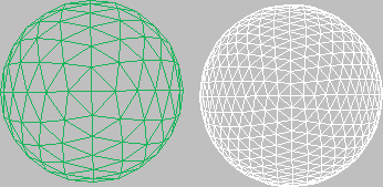
You can repeat this process, subdividing multiple times. Each subdivision increases the number of patches, which become increasingly smaller. The following figure is an example of modeling a highly subdivided surface.
To subdivide an edge:
- At the Edge sub-object level, make an edge selection.
A single edge is indicated by its coordinate axis or transform gizmo at the center of the edge. For multiple edges, the axis icon is at the center of the selection set.
- Optionally, turn on Propagate to maintain surface continuity.
- Click Subdivide.
The edge selection is subdivided. Each new edge is on the boundary of a new, smaller patch.
To add a patch:
- At the Edge sub-object level, select an open edge (one that bounds a single patch, and therefore is not shared with another patch).
- Click Add Tri or Add Quad.
A new patch is added to the surface.
To unlock interior edges of selected patches:
- At the Patch sub-object level, select one or more patches.
- Right-click the selection and choose Manual Interior from the pop-up menu.
The check mark moves from Auto Interior, the default, to Manual Interior. Interior edges and their vertices are now unlocked. If you now transform the patch, the interior edges remain static. To transform the interior vertices, see the following procedure.
To transform interior vertices:
- At the Patch sub-object level, select one or more patches.
- Right-click the selection and choose Manual Interior from the pop-up menu.
The check mark moves from Auto Interior, the default, to Manual Interior.
- Switch to Handle level.
The interior vertices appear as yellow squares.
- Transform the interior vertices of the selected patches.
To anchor a patch:
- At the Patch (Patch) level, before you begin the weld, select the patch you want anchored.
- Return to Vertex level and weld the vertices.
When the weld occurs, the anchor patch remains fixed while the other patch moves to make the weld.
By default, the welding process shifts the geometry of both patches to a common center. You can anchor one patch so that the other patch moves to its location when the weld occurs.
To create a new element, do one of the following:
- Shift+drag one or more patches.
- Shift+extrude one or more patches.
- Shift+extrude one or more edges.
- Shift+drag an element.
Interface
Selection rollout
For information about these settings, see Selection Rollout (Editable Patch).
Soft Selection rollout
For information on the Soft Selection rollout settings, see Soft Selection Rollout.
Geometry and Surface Properties rollouts
The Geometry rollout provides functions for editing a patch object and its sub-objects, and the Surface Properties controls let you modify the object's rendering characteristics. For detailed information on sub-object-specific controls, see the topics in this section.