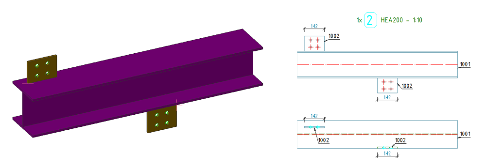
Use the options available in the Arrangement on the Drawing area of the Dimension Request tab to create better positioning relative to the objects presentation.
Dimension line must not overlap the total geometry
Select whether the dimension chain should be free of intersections with the dimensioned local geometry or with the total geometry of the detail.
| Option | Example |
|---|---|
| Abbreviation:
G (Global)
Dimension line must not overlap the total geometry - box unchecked |

|
| Abbreviation:
L (Local)
Dimension line must not overlap the total geometry - box checked |
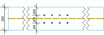
|
Arrange the dimension line above and not below
This option defines whether the dimension chain is placed above or below a detail view. In the vertical detail views above is left and below is right.
| Option | Example |
|---|---|
| Abbreviation:
B (Bottom)
Arrange the dimension line above and not below - box unchecked |
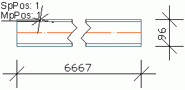
|
| Abbreviation:
T (Top)
Arrange the dimension line above and not below - box checked |
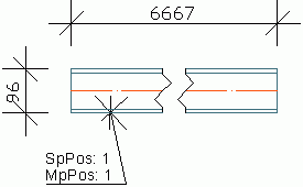
|
Create a separate dimension chain for each item marked with*
If this option is checked, a dimension chain is created for each single object detected in the model (e.g. bolt pattern). If this option is not checked, all the detected objects are dimensioned in one dimension chain.
| Option | Result |
|---|---|
| Abbreviation:
A (All)
Create a separate dimension chain for each item marked with* - box unchecked |
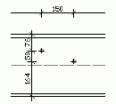
|
| Abbreviation:
S (Single)
Create a separate dimension chain for each item marked with* - box checked |
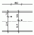
|
A bolt pattern creates only one dimension chain because it is just one object.
Example
Mp X - Extreme GTA - a dimension chain with the maximum dimensions of a main part.
G - no intersection with the total geometry
T - the dimensions are placed above the detail
A - all detected elements are dimensioned in one single dimension chain
Automatically separate
This option creates separate dimension chains for each individual object (the object can be a feature, such as a cut or a cope or it can be an attached beam or plate) on the drawing. Use this option to also automatically arrange the dimensions on the corresponding side of the targeted objects.
Examples
Cope cut found at beam ends:

Attached plates that require individual dimensions:
