Learn how to use, modify and update manual dimensions on Advance Steel detail drawings.
In addition to the dimensions created automatically during detailing, Advance Steel also provides a wide set of tools that allow you to manually edit existing dimensions or create new ones.
When creating new manual dimensions on Advance Steel drawings, it is strongly recommended to use the Advance Steel tools instead of the AutoCAD Linear Dimensions. Advance Steel dimensions have several key attributes compared to the AutoCAD ones, such as:
- Showing the correct value, regardless of the drawing scale.
- Dimensions moving or scaling along with the detail views.
- Taking clipping into consideration.
- Making them smart dimensions that update if the geometry of the objects changes.
The main limitation of AutoCAD dimensions, besides the fact that they will never update or follow an Advance Steel detail view, is the scale - which needs to be inputted manually for each dimension. Advance Steel drawings are scaled down when you add them to the sheet, matching the scale of the view, even if the views on the sheet are each at different scales.
Smart Dimension Points
Smart dimension points (or preferred) are dimension points located on the reference object, that connect to an object dimension, allowing the Advance Steel manual dimension to grip to that object when drawings are updated. For example, a dimension point created on a plate corner will adjust if the plate is moved or if its geometric size is modified in the 3D model and it will be updated on the drawing - the dimension created in the 2D drawing is linked to the 3D model point associated to that corner of the plate.
Create Parametric Dimensions
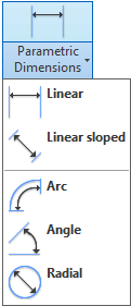
 Parametric Dimensions panel
  Parametric Dimensions drop-down:

Each dimension is designed to work for a specific dimension type, and, depending on the dimension you use, you will be asked to choose:
- Dimension points
- The position of the dimension line or dimension text
- Helper points (e.g. Arc dimensions)