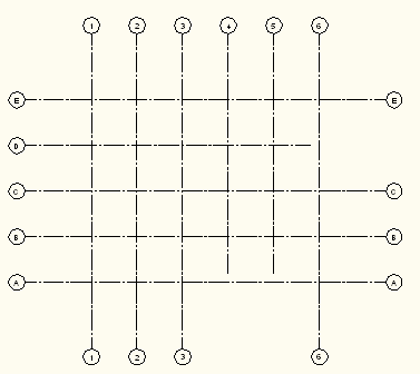
You can define a different number of grid lines for each of the four grid sides.

- Click


 .
. Alternatively, you can select the Enhanced Custom Column Grid tool on the Design Tool Palette.
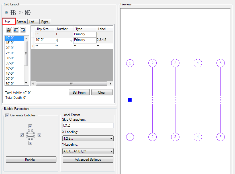
- First, generate the grid layout for the side that has the larger set of grid lines. For example, if you want to create a grid that has lines 1, 2, 3, 4, 5 on top, and 1, 3, 4, 5 on the bottom, you first select the Top tab and enter 4 grid bays at the desired distance.

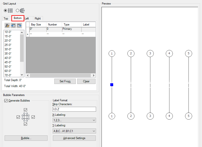
- Then switch to the Bottom tab. You will see, that although no grid bays have been defined yet, all grid lines from the Top side have been drawn through to the bottom. This is the default setting.
 Tip: The preview window displays all grid lines defined in the currently selected tab in purple. Grid lines defined previously in a currently non-active tab are displayed in black.
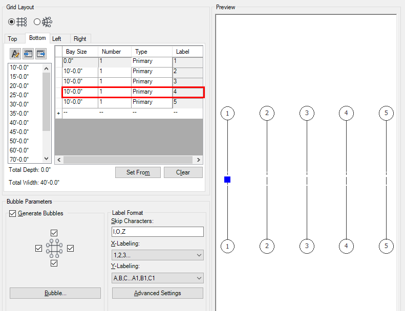
 - Now, start adding bays for the bottom part of the grid with the same bay size as the top ones. You will see that the color of the grid lines changes from black to purple, indicating that these lines are defined in the bottom part. Note: The first and the last lines of the grid extend to both sides by default.
At this point, you have an incomplete set of grid bays for the Bottom tab. If this already gives you the configuration you need (as in the example below), you can now either place the grid in the drawing, or switch to the Left/Right tabs, in order to define the horizontal lines.

- If this does not give you the desired result, proceed filling in the bottom part of the grid, until you have one grid bay less than in the top part. (You have to do this because the final grid line always is drawn at both sides). In this example, we added 4 bays (5 grid lines) for the top. If you want to have one less for the bottom, add only three bays for the bottom part:

-
In order to leave out one line, you must enlarge the bay to double its size. For example, if you want to leave out grid line 2, then the first bay must be doubled from 3000 mm to 6000 mm:

Now, the first bay spans two bays at the bottom, and as a result, you have only four grid lines instead of five. You can now either switch to the Left tab to edit the other grid axis, or you can press Enter to place the grid in the drawing.
Note: You can also work the other way around and create the full set of grid lines on the Top tab, copy-and-paste them to the Bottom tab, and then start to delete and edit individual rows as necessary.